首次飞行与调参
解锁、检查单、调参与 AutoTune
- 新手起飞提示
- 解锁与上锁
- AutoTune 自动调参
- 飞行前检查单
- 测量振动
- 解锁前安全检查(Pre-Arm)
- 调参
- 首次飞行与调参
- 横滚 / 俯仰调参
- 设置悬停油门
- 特技多旋翼
- automatic-tuning-with-autotune
- Save Trim / Auto Trim
- calibrating-an-airspeed-sensor
- 地面共振
- IMU FFT
- IMU 陷波滤波
- 遥控器调参旋钮
- 评估整机调参
- 高环路速率调参
- 室内飞行
- 初始调参飞行
- 输入整形(Input Shaping)
- navigation-tuning
- new-roll-and-pitch-tuning
- QuikTune
- roll-pitch-controller-tuning
- 调参前准备
- tecs-total-energy-control-system-for-speed-height-tuning-guide
- 油门增益(Throttle Boost)
- 推力损失与偏航不平衡告警
- 调参流程说明
新手起飞提示
新手起飞提示:
- 选择开阔无风或小风场地;远离人群与障碍
- 先低高度小杆量熟悉;准备好随时切 RTL / Land
- 一次只改一个变量(参数/重心/螺旋桨)
- 出现异常振动、漂移、电流异常立即降落排查
- 记录日志,飞后用日志工具复盘
中文精译(主干)· 原文 ac_tipsfornewpilots · CC BY-SA 3.0
解锁与上锁
解锁(Arm)允许电机旋转;上锁(Disarm)切断动力。错误解锁是严重安全隐患。
要点
- 通过解锁前检查(Pre-Arm)后,使用设定的解锁手势/开关解锁。
- 默认常见为油门最低时内八/外八偏航组合(以你的配置为准)。
- 螺旋桨安装前务必完成传感器与遥控校准;装桨后清空螺旋桨旋转平面内的人员。
- 上锁确认电机停转后再靠近机体。
危险:旋转螺旋桨可造成重伤。始终假设系统可能意外解锁。
中文精译(主干)· 原文 arming_the_motors · CC BY-SA 3.0
AutoTune 自动调参
AutoTune 通过试飞自动估计姿态控制相关参数,改善 Stabilize/AltHold 等模式下的手感与稳定性。
警告:AutoTune 过程中机体会主动激励,请在开阔场地、充足电量、良好定位下进行,并随时准备中断。
- 先完成基础校准与可接受的粗调
- 按文档切换到 AutoTune 并完成轴选择
- 结束后保存参数;不佳时可恢复备份
中文精译(主干)· 原文 autotune · CC BY-SA 3.0
飞行前检查单
飞行前检查单(建议打印或做成地面站清单):
- 机架/螺旋桨无裂纹,桨向正确,螺丝紧固
- 电池电压与健康状态,连接可靠
- 遥控与飞控电量;链路与失控保护已测
- GPS / 罗盘正常;Home 位置合理
- 飞行模式开关位置正确;可一键 RTL
- 场地净空、天气与法规允许
- 人员位置与应急程序明确
中文精译(主干)· 原文 checklist · CC BY-SA 3.0
测量振动
[copy 这是什么? wiki 目的地="cop访谈机,飞机,rover,dev,sub,planner"]
自动驾驶器有对遵照振动敏感的 知道了解释了吗? 这些加速计值与气压计和 GPS数据估算机体位置. 与过度 振动,估计具有普遍性 并导致非常糟糕 依赖于准确定位的模式中的性能(例如: 受命团团团团团团团团团团团团脾气团团团团团团团团团团团团团团团团团团团团团团 哪团团团团团团团团团团团团团团团团团团团团团团团团团团团团团团团团团团团团团团团团团团团团团团团团团团团团团团团团团团团团团团团团团团团团团团团团团团团团团团团团团团团团团团团团团团团团团团团团团团团团团团团团团团团团团团团团团团团团团团团团团团团团团团团团团团团团团团团团团团团团团团团团团团团团团团团团团团团团团团团团团团团团团的整个团团 不知道团团团团团团团团团团团团团团团团团团团团团团团团团团团团团团团团团团团团团团团团团团团团团团团团
这些指示解释了如何测量振动水平. 如果你们 发现他们没有容忍,
地面站实时视图
地面站可以显示振动和剪切的实时视图. 如果使用任务规划器点击HUD上的"Vibe"显示当前振动水平.

震级低于30m/s/s通常可以接受. 30米/秒以上级别可能60米/秒以上的问题和水平几乎总是存在位置或高度控点的问题。
Vibe 数据闪存日志消息
请检查access-date=中的日期值 (帮助) Vibe 水平大多低于 30m/s/s
进行至少一个正常飞行(即不只是温柔的盘旋) 几分钟后,并 ** 下载数据闪存日志 **。
使用飞行任务规划员或其他地面站绘制VIBE信息 维贝X,维贝Y和维贝Z值. 这些显示 主加速计的输出以毫秒/秒为单位。 下面的图像,拍摄 3DR IRIS显示的正常水平低于15m/s,但 有时峰值为 30m/s/s。最大可接受值似乎为 低于30m/s/s(见下文第二幅图)。
图形 Clip0、 Clip1 和 Clip2 值, 每次增加一次 加速计达到最大限值(16G)。 理想情况 在整个飞行中,数字应为零,但数字低( < 100) 特别是在硬着陆时 经常 记录中数字的增加表明震动严重 问题** 我告诉你应该解决**。
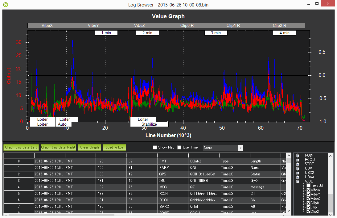

这是一辆车在估计位置时出现问题的例子 到高震动。

侏儒学中的振 Malay 计算振动水平的算法可见除其它外。AP协商一致意见.cpp 的 calc 振动 和 clipping()方法旁边,但简言之,它涉及计算 加速计读数是这样的:
- 从主 IMU 获取原始 x、 y 和 z 加速计值
- 高通过滤5hz的原始值,以删除机体 移动并创建 x,y 和 z 轴的“accel vibe floor”。
- 计算最近算法值与 accel vibe 地板.
- 平方上述差异,在 2hz 进行过滤,然后计算 平方根(x、y和z)。 最后三个值是 出现在 VIBE msg 的 VibEX, Y 和 Z 字段。
当在日志中看到振动时,首先要看的是剪辑. 若剪辑为0, 这表示被检测到的振动并没有压倒IMU。
在排除振动时,将振动的轴视为寻找问题的凝视点:
如果X和Y都很高,那么你可能会遇到运动轴承或道具平衡的问题. 或者你可能需要更多的/更好的整体振动 挡住你的FC。 如果 X OR Y 是高,那么你可能会有一个问题 与你的FC 安装。 也许有窃听器在FC上爆炸 或者限制它 或者,也许你的振动坝 在一个轴上比另一个未经许可。 如果你有Z振动,你可能会遇到螺旋桨(bent label)或电动机中垂直播放的轨道问题。
还考虑到一些飞行条件/机体会有不同的自然振动. 如果振动在徘徊中看起来不错,但随着速度的增加, 可能与机体有空气动力问题,或者在风中,
找"莲丝"
莲丝发生于机体姿态估计不正确,即使飞行员指挥水平飞行,也导致机体大幅倾斜。 相互合作的目的是,通过对每个估计系统(即每个AHRS或EKFs)的罗尔和皮奇姿态估计进行比较,可以确认这种变化。 态度估计应该在几度之内
- 下载数据闪存日志,在地面站的日志查看器中打开
- 比较A恪守HHRS2. Roll, NKF1[0]. 卷和NKF1[1]. 如果使用 E恪守F2 或 AHRS2. 卷, XKF1 [0] (中文(简体) ). 滚动和XKF1[1]. 如果使用 EKF3 滚动
下面的图像显示一个典型的日志,其中的态度非常吻合

使用 FFT 仍在进行的高级分析
关于如何收集大量IMU数据并进行FFT分析以确定振动最强的频率的说明,请参看**用“Raw IMU日志”测量振动**页。
IMU 数据闪存日志消息
对于没有包含 Vibe 消息的非常古老的ArduPilot 版本,可以直接检查 IMU 值
确保设置 **LOG BITMA 1920K ** 参数以包含 IMU 数据,从而将加速计值记录到数据闪存日志
在稳定模式中飞翔您的摩托并尝试保持水平悬浮(它不需要完全稳定或水平)
** 下载数据闪存日志和** 下载完成后,使用特派团规划员的“审查a” 日志"按钮打开日志目录中的最新文件( 这是最后一个) 数字将是您在梵文中下载的日志编号 我们下载了日志 # 1 所以文件名将在 1.log 中结束 。
当日志浏览器出现时,请向下滚动,直到找到任何 IMU 留言。 点击行的 AccX 并按绘制此数据左边 提供资源。 就这一问题重复 AccY 和 AccZ 列生成一个像 见下文。
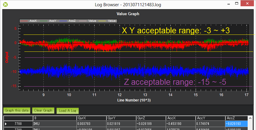
检查左边的缩放并确保您的振动水平 3 和3 。 不得拒绝,不得拒绝。 范围为 -15 至 -5. 如果它非常接近或超过这些限制 有关可能的解决方案,请参考** 核查大坝**页。
在完成上述工作后,请按照特派团规划员的标准行事。 参数页(您可能需要按下连接按钮) 并设定日志比特马斯返回“ 默认 ” 。 这很重要,因为 特别是在APM记录方面,需要大量的CPU资源, 如果真的不需要的话 记录这些是浪费

译自 ArduPilot Copter「Measuring Vibration」· 查看原文 · CC BY-SA 3.0
解锁前安全检查(Pre-Arm)
解锁前安全检查(Pre-Arm Safety Checks)在解锁前验证传感器、校准、配置与安全条件。失败时地面站/HUD 会提示原因。
- 加速度计 / 罗盘校准是否完成且一致
- GPS 定位质量(若模式需要)
- 遥控校准与失控保护
- 电调、电池、SD 卡、参数完整性等
不要用“关闭检查”来绕过问题,除非你完全清楚风险(例如台架测试)。
中文精译(主干)· 原文 common-prearm-safety-checks · CC BY-SA 3.0
调参
调参目标是让机体稳定、跟杆跟得上且无振荡。Copter 提供分步流程、QuikTune、AutoTune 与滤波相关工具。
- 先保证振动可接受(见「测量振动」)
- 按调参流程或 AutoTune 做姿态环
- 再调整输入整形、油门与导航相关参数
调参不是一次完成:换桨、换电池、改重心后都可能需要重做。
中文精译(主干)· 原文 common-tuning · CC BY-SA 3.0
首次飞行与调参
首次飞行与调参覆盖从解锁前检查到起飞、基础手感与后续调参的流程。
建议顺序
- 通过 Pre-Arm 检查
- 在安全场地完成检查单
- 首次起飞:优先 AltHold / Loiter(视定位情况)
- 检查振动,必要时减振
- 按调参流程或 AutoTune 改善姿态与导航响应
新手上机请降低期望:先稳定起飞—悬停—降落,再谈航线与自动任务。
中文精译(主干)· 原文 flying-arducopter · CC BY-SA 3.0
横滚 / 俯仰调参
可能需要手动调谐,以便在Autoune运行前提供稳定的调谐,或者如果Autoune不能产生可接受的调谐. 下面的过程可以 Gramroll 和 pitch 同时完成 一个快速的手动调只要飞机对称如果飞机不对称,则应单独进行滚动和投射。
飞行员应特别注意确保**ATC THR MI砂拉越**和**MOT THST HOVER ** 在开始手动调谐前正确设置。
当振荡开始时,不会产生大量或突然的棒状输入. 55. 在使用非常缓慢和小的滚子和投球投入控制飞机位置的同时,顺利减少油门以降落飞机。 每个轴 :
如果该车已经在一个轴上振荡 收到,首先降低P,D,我用50%的步数,直到稳定,然后开始手动调谐.
- 在观测到振荡之前书面材料增加50%
- 在振荡消失之前将 D 值减少10%
- 将D任期再减少25%
- 在观测到振荡之前,将P值增加50%
- 在振荡消失之前,将 P 值减少10%
- 将P任期再减少essa 25%
Each time the P term is changed set the I term equal to the P term. Those parameters can be changed on ground and preferably disarmed. A confident pilot could set them in flight with GCS or transmitter tuning knob (see Transmitter based tuning page for setup of this feature).
If using Transmitter based tuning, set the minimum value of the tuning range to the current safe value and the upper range to approximately 4 times the current value. Be careful not to move the slider before the parameter list is refreshed to recover the set value. Ensure the transmitter tuning is switched off before setting the parameter value or the tuning may immediately overwrite it.
Video of in-flight tuning
width: 100% url_parameters: ?start=145
【本页后半部分仍为英文原文摘录,补译中。】
译自 ArduPilot Copter「Manual tuning of Roll and Pitch」· 查看原文 · CC BY-SA 3.0
设置悬停油门
科普特包括自动学习Hover Throttle(以前称为"中间油门"). ##MOT THST 盖尔# 其原因如下: 缓慢地向上移动, 其原因如下: 其原因:
如果您想要手动设置 **MOT THST Hover **值,最好下载一个数据flash日志,并将值设定为CTUN中看到的值. THO球场. 值通常在0.2至0.6之间,但如果涂装机的功率对重量比率非常高,则可能较低.
如果您出于某种原因想要禁学, 您可以设置 ** MOT HOVER LEARN ** 参数为0.

【本页后半部分仍为英文原文摘录,补译中。】
译自 ArduPilot Copter「Setting Hover Throttle」· 查看原文 · CC BY-SA 3.0
特技多旋翼
此页面是正在进行的工作
有了适当的机体配置和仔细的调制,可以得到精确的,具有攻击性的多校对器,用于**ACRO模式**的赛车或航空比赛.
第一个要求是一个非常坚固的车架来抵抗共振振动,以及一个能对重量比率产生高有望的动力系统. 用较小的( < 6英寸对角马达距离)框架最容易获得。
显然,赛车迷你方格框已经满足了这些要求,通常是. 使用ArduPilot固件的优点是能够将攻击性飞行特性与FENCES,后续模式,RTL模式等自主特性相结合. 在某些情况下甚至可以包括**反对**。
已在 设置
跟随正常的ArduCopter 维基制定准则**。 然而,获得最佳业绩的关键将取决于**调音和噪声过滤装置的谨慎和精确度。。从过滤中获取最高性能的关键将是使用双直径DSHOT ESCs来提供单个的马达 rpm,用于设置单个的 Notch 备案器来跟踪每个马达(参见常识几何.
需要全球定位系统吗?
您不需要GPS来以许多科普特模式飞行(ACRO, STABILILZE, ALTHOLD, etc.). 但是,在使用GPS/Compass使需要位置信息(如LOITER或RTL)或栅栏等模式能够使用时,必须尽量考虑和补救单元的放置以避免动力系统的磁干扰和/或RC系统对GPS性能的RF干扰。
带有全球定位系统的侵略性飞行的后果
If you do include a GPS for the advance mode capabilities, then there are some potential consequences that can occur when switching to position holding/tracking modes after aggressive maneuvering in modes like ACRO. These are:
- EKF Failsafes occurring
- Large position errors, ie like switching to RTL and then overshooting HOME position by very large amount, or tracking waypoints in a mission with large positioning errors
Both of these are due to errors generated by high accelerations resulting in GPS miss-measurement of velocities, resulting in the navigation filter declaring itself unhealthy (EKF Failsafe), or very bad position estimates.
These issues CAN be reduced/eliminated by either setting the EK3_GLITCH_RAD = 0 , or increasing FS_EKF_THRESH, or both. But this should be used only if experiencing the above problems,and with caution, since it can degrade positioning accuracy rather then improve it in some cases, and/or allow EKF degradation to occur to the point of possible vehicle instability.
Optimal Tuning (Using fast attitude loop feature)
Once initial setup and tune has been done. high-loop-rate-tuning can be attempted to optimize the tune for aerobatics
【本页后半部分仍为英文原文摘录,补译中。】
译自 ArduPilot Copter「Aerobatic/Racing Multicopter」· 查看原文 · CC BY-SA 3.0
automatic-tuning-with-autotune
上游文档:automatic-tuning-with-autotune。
Save Trim / Auto Trim
风当然对你的机车有很强的影响 并且会把它推首先 然而,你可能也发现,在稳定模式下飞行时,即使在无风的环境中,你的直升机使它们能够总是朝同一方向飘去。 这基本上可以使用"拯救Trim"或"自动Trim"功能来纠正.
说明:
对于大多数用户来说,这种程序是不必要的,因为**加速度计校准**能很好地设定修饰值.
AHRS 自动转盘恰当地
使用AHRS AutoTrim,在稳定盘旋中飞行时,卷与各国的校正被捕获. 设置 a通用辅助功能切换到"在飞行AHRS修剪调整中"("182")的一点是. 我们将使用CH7如下:
- 等等 请检查url=值 (帮助) 那么您的CH7开关在1800以上

- 设置您所选择的频道
RCx 选择至"AHRS Auto Trim" (182),使用Mission Planner的Aux函数屏幕并按下""Write Params"按钮. 见通用辅助功能关于指定任何RC频道选项的细节。 - Find a wind free environment with sufficient space to fly your copter without crashing into something.
- Put the vehicle in manual Stabilize/AltHold mode or a position hold Loiter/PosHold mode (recommended).
- Arm the vehicle and lift into a hover. The vehicle must be flying in order to enable autotrim. Flip the switch that you setup (CH7) to its High position (>1800us). "Autotrim running" message will be sent to the GCS.
- If in a manual mode, fly your copter for about 25 seconds in a stable hover in position, keeping it from drifting with the pitch and roll sticks. As the trim is adjusted, less and less corrections with the sticks will be required. If using a position hold mode, take off and let the copter hover in place while not touching the sticks.
- Once satisfied, flip the switch low, saving the trims, and land. "Trim save" message will be sent to the GCS.
- Take off in AltHold mode and check if your copter is flying level now. If not repeat steps 4 - 7 again.
说明:
You can manually set the trim by modifying the **AHRS_TRIM_X ** and **AHRS_TRIM_Y **. Roll trim is **AHRS_TRIM_X **, Pitch trim is **AHRS_TRIM_Y **. Both values are in radians with left roll and forward pitch being negative numbers.
说明:
It is nearly impossible to get rid of all drift so that your copter remains completely motionless without any input. It may be preferable to yaw the copter 90 degrees and holding that orientation for about 6-7 seconds each time so that any external disturbances will get cancelled out, resulting in a better trim.
Save Trim
说明:
the above AHRS AutoTrim method is preferred since it does not involve moving transmitter trims after RC calibration.
Save trim involves essentially transferring your radio transmitter's trims into the autopilot's AHRS trim (the AHRS_TRIM_X ** and **AHRS_TRIM_Y ** parameters), the same values that the AHRS AutoTrim method above adjusts. Normally, once **common-accelerometer-calibration is done, you never want to change the transmitter's trims, but in this case it is done temporarily. The "Save Trim" function ("5") is assigned to any free RC channel, usually a switch based one, using an common-auxiliary-functions. For the example below, Channel 7 will be used.
- Check that your CH7 switch goes above 1800 on the MissionPlanner's Setup > Mandatory Hardware > Radio Calibration screen
- Set your chosen channel's
RCx_OPTIONto "Save Trim" (5) using Mission Planner's Aux Function screen and press the "Write Params" button. See common-auxiliary-functions for details on assigning options to any RC channel.

- With your CH7 switch in the off (Low) position, fly your copter in Stabilize or AltHold mode and use your transmitter's roll and pitch trim to get it flying level
- Land and put your throttle to zero
- Release the roll and pitch sticks and switch the CH7 switch high for at least 1 second. The words "Trim saved" should appear in the MP's Flight Data screen's Messages tab
- Reset your transmitters roll and pitch trims back to the center and fly again and it should fly level now. If it does not repeat steps 3, 4 & 5
说明:
Save Trim also works while **Simple or Super Simple mode ** is enabled, but take care not to change the vehicle's heading between landing and switching CH7 high, since the trim will be saved relative to the vehicle's heading at that moment.
Desktop method
The trim can also be updated by setting the vehicle level, connecting to the Mission Planner (or perhaps other ground stations) and selecting Initial Setup, Mandatory Hardware, Accel Calibration and pushing the lower "Calibrate Level" button.

Please note though that making the HUD level while the vehicle is on the ground does not necessarily mean it won't drift horizontally while flying because of other small frame issues including the flight controller not being perfectly level on the frame, CG placement, an/ord slightly tilted motors.
【本页后半部分仍为英文原文摘录,补译中。】
译自 ArduPilot Copter「AutoTrim」· 查看原文 · CC BY-SA 3.0
calibrating-an-airspeed-sensor
上游文档:calibrating-an-airspeed-sensor。
地面共振
飞机在降落时或起飞前往往会摇摇欲坠。 这种现象被称为地面共振振荡,是由姿态控制器与弹性帧或弹性起落架相互作用引起的. Ardupilot允许您减少卷,投子和yaw轴中姿态控制器的增益,以在登陆时减轻PID环路,从而消除这种不稳定性. 这样做应当谨慎,因为我们不想在起飞时破坏我们的滚球和投球姿态控制性能。 起飞后上半秒 我们可能不太保守 因为起飞后上半秒 就会影响对黄蜂的控制
用于处理地面共振振 等等 三个参数是:AT以便向您开放, ATC 土地 P MULT,以及ATC 土地 Y MULT这提供了减少Rll,Pitch和Yaw pid在当地收益的能力.
评估地面共振振荡
- 在稳定模式窖里装油门
- 将节流阀提升到发动机增加到MOT SPIN MIN的地步
- 观察轴线的振荡,
- 滚开ATC_LAND_Y_MULT to 0.5
- Revaluate Roll and Pitch oscillation for improvement
- Back off axis where oscillation is observed in 25% steps until oscillation is manageable.
说明:
Extreme care should be taken if ATC_LAND_R_MULT or ATC_LAND_P_MULT is reduced below 0.5.
[copywiki destination="copter"]
【本页后半部分仍为英文原文摘录,补译中。】
译自 ArduPilot Copter「Preventing Ground Oscillation」· 查看原文 · CC BY-SA 3.0
IMU FFT
[复制维基目的地="copter,plane"].
基于 FFT 的调谐音节设置
说明:
此功能包含在带有2MB内存的自动驾驶中. 检查您的自动驾驶器二进制特性用于确定您的自动驾驶员是否有此功能(GyroFFT)。 另外,只能设置一个基于FFT的Notch.
ArduPilot 预设了所有的意愿 行了 。 最初需要设置的只有:
- 设置 **FFT ENBEL ** = 1 以启用FFT引擎. 这需要您重新启动自动驾驶, 之后将启用 FFT 支持, 其他 FFT 参数应在您的GCS 中可见 。 在默认参数设置下, FFT 引擎将运行一个自查, 以查看您的硬件上的频率匹配 。 如果你没有看到任何 FFT 错误, 那么事情是正常的。
- FFT启用后,最好先进行试飞,检查飞机特定噪声频率是否被捕获 让CPU负载监测. 见初步分析飞行**. 通常情况下,结果会显示清晰的噪声识别和可接受的 cpu 加载, 然后你可以使用 FFT 驱动 ** 谐波 Notch通过设置这些参数:
- 设置 **INS HNTCH ENTCL**和/或**INS HNTC2 ENTCL ** = 1 用于调谐音节 = 1 用于调谐音节
- 设定 **INS HNTCH MODE**和/或 **INS HNTC2 MODE ** = 4用来使用FFT检测到的频率来控制口腔频率.
- Set **INS_HNTCH_REF ** and/or **INS_HNTC2_REF ** = 1 to set the harmonic notch reference value, which for FFT analysis generally means no scaling
- The harmonic notch reference frequency parameter, **INS_HNTCH_FREQ ** and/or **INS_HNTC2_FREQ **, is used to indicate the lowest motor speed for which the ESC telemetry should be used to dynamically set the harmonic notch reference frequency.
For most uses with other FFT-related advanced parameters at their default, this is all that is required. The user can do optimization of the filtering setup by analyzing the test flight logs and adjusting notch bandwidth, if desired, by following the **In-flight FFT Advanced Setup ** instructions.
说明:
Setting up the FFT parameters can be done automatically using the RCx_OPTION auxiliary function "162" on a transmitter switch. Set the function to a switch on the transmitter. Hover the vehicle, switch it on (high) for 30 seconds, and switch back low and land. The parameters will have been set up and the switch function removed. NOTE: do not use this feature in firmware version 4.3!
说明:
Using In-Flight FFT can result in poorer performance than a properly set up **Throttle-Based ** notch filter since the FFT computations take time and can lag the actual required center frequency. In-Flight FFT is useful when the rotor frequencies of the vehicle vary widely as in heavy lift vehicles operating with high and low loads. It can be useful in setting up **Throttle-Based ** notch filters, however, see **In-flight FFT Advanced Setup ** instructions for more information.
FFT Dynamic Harmonic Notch Frequency Tracking
FFT mode tracking sets the base frequency to the largest noise peak. Normally, when multiple harmonic notch filters are then enabled, the center frequency of each harmonic is locked to the base frequency of the first filter as an integer multiple, as determined by INS_HNTCH_HMNCS **. The bandwidth of the notch (and any enabled harmonic notches) will maintain a ratio set by the _FREQ/_BW params as the center frequency moves. Setting bit 1 of **INS_HNTCH_OPTS, or INS_HNTC2_OPTS, will enable each harmonic filter to track the three largest noise peaks, individually.
说明:
setting bit 1 of the notch options will also change the default value of **INS_HNTCH_HMNCS ** to 1 instead of its normal 3. This is to maintain backwards compatibility with previous firmware versions. You can set **INS_HNTCH_HMNCS ** back to 3, or whatever is desired, after setting bit 1 of **INS_HNTCH_HMNCS **
警告:
If you set bit 1 of INS_HNTCH_OPTS, or INS_HNTC2_OPTS, the bandwidth should not be half the frequency(default). It should be greatly reduced as more notches (3x more since now tracking three noise peaks) cause more phase lag (i.e. latency), thus the bandwidth needs to be reduced to maintain a reasonable phase lag, else oscillation and a poorer tune will result despite the more accurate filtering compared to throttle-based filtering. The suggested starting point is setting the _FREQ/_BW params to 4/1 ratio instead of the default 2/1. This is because for notch filters, a wider bandwidth causes a greater phase lag per notch. You can also use the Filter Tool to check the phase lag for your chosen filtering settings. If your phase lag is higher than it was with the single peak filtering, then you can try reducing the bandwidth even further, balancing the phase lag and the amount of noise in the system.
FFT Options
There are two options that can be selected by setting the appropriate bit in the FFT_OPTIONS parameter that affect FFT operation:
Post Filter Chain FFT Analysis Window
Normally, the FFT analysis for adjusting the center frequency is done by measuring the noise directly at the output of the unfiltered gyro data. However, if bit 0 of FFT_OPTIONS is set, then the measurement window takes into account the effects of the low pass filter and any configured notch filter(s). This is useful if there is high-frequency noise, which impacts the control response less than lower-frequency noise due to the low pass at the end of the filter chain but may be targeted by the FFT measurement. Setting this bit will only track those lower frequency, and more critical, noise peaks.
Motor Noise Check
If bit 1 of FFT_OPTIONS is set and ESC motor rpm telemetry is available, then the measurement window for the FFT is centered about the motor(s) frequency as reported by ESC telemetry. This will generate a GCS warning message if noise from any motor greater than 40db is passing through the filter chain, and identify its level, motor number, and frequency. This bit must be used with bit 0 also set.
Typical Use
A typical use of the FFT notch filter is in addition to other dynamic harmonic notch filters (Throttle, ESC, or RPM-based). In these configurations, using the post-LPF FFT Window FFT_OPTIONS bit will yield the best overall filtering results by positioning the FFT filter to target noise not filtered by the other notch filter and gyro LPF (INS_GYRO_FILTER.
Additional Information
For those interested in the details of how this feature works and tradeoffs in some of the advanced parameters, not normally adjusted by users, the **In-Flight FFT: How it Works ** document describes the operation and these advanced parameters.
【本页后半部分仍为英文原文摘录,补译中。】
译自 ArduPilot Copter「In-Flight FFT-Based Harmonic Notch Setup」· 查看原文 · CC BY-SA 3.0
IMU 陷波滤波
[复制维基目的地="copter,plane"].
用动态谐音 Notch 过滤器管理 Gyro 噪声
如下文所述。振动大坝主题,管理ArduPilot自动驾驶装置中的振动对于对飞机进行可预测的控制极为重要。 设施通常利用机械振动坝对自动驾驶员进行内部或外部的振动,以便消除最严重的振动。 然而,机械制坝只能走这么远,必须使用软件过滤来清除更多的噪音.
对自动驾驶员来说,振动噪声看起来类似于其他任何扰动(如风,扰动,控制链路slop等),自动驾驶员为了控制飞机必须予以补偿. 这阻碍了姿态控制循环的最佳调整和性能的降低.
[站点维基="飞机"]. ArduPlane为噪声提供了两种过滤机制: [/现场] [站点维基="copter"]. ArduCopter为噪声提供了三种过滤机制: [/现场]
- 加速计信号上的低通滤波器,由互联网档案馆的存檔,存档日期2013-09-02.,以及陀螺仪信号,由INS GYRO FILTER (英语).,
#. 陀螺仪信号上的谐所通过的过滤器INS_HNTCH_ENABLE ** and/or **INS_HNTC2_ENABLE **,
[site wiki="copter"]
#. Attitude rate PID loop filtering of reference inputs, controlled by **ATC_RAT_RLL_NTF, ATC_RAT_PIT_NTF and ATC_RAT_YAW_NTF. Attitude rate PID loop filtering of error inputs is controlled by ATC_RAT_RLL_NEF, ATC_RAT_PIT_NEF and ATC_RAT_YAW_NEF. For altitude acceleration control, use PSC_ACCZ_NTF and PSC_ACCZ_NEF on firmware before 4.7.0, or PSC_D_ACC_NTF and PSC_D_ACC_NEF on firmware 4.7.0 and later.
[/site]
As discussed in common-measuring-vibration section, there are basically two classes of noise/vibrations: those generated within the bandwidth of the gyros/accelerometer sampling and noise above those frequencies which are "aliased" down to within that bandwidth and can cause the "leans". The aliased noise must be eliminated at the source with improved mounting or frame rigidity, but the above filters can deal with the other sources, typically generated from the motor/propellers at their rotation frequency and its harmonics.
For multicopters and QuadPlanes, virtually all vibrations originate from the motor's rotational frequency. For helicopters and planes, the vibrations are linked to the main rotor/prop speed.
ArduPilot has support for two dynamic harmonic notch filters whose filter frequency can be linked to the motor rotational frequency for motors, or the rotor speed for helicopters, and provides notches at a primary frequency and its harmonics. And support for eight static notch filters: four at the rate PID target inputs and four at the rate PID error inputs. These are useful for eliminating frame harmonic resonances.
While the lowpass filters can effectively diminish the impact of this noise, having low frequency set points creates a lot of phase lag and therefore reduces how aggressive the tune can be before oscillation occurs, which results in a poorer tune.
For the gyro based rate controllers, this reduces their ability to respond to fast disturbances. If the gyro lowpass filter can be set higher, the phase lag induced is lower and the tune can be more aggressive. But this allows more noise and vibration, effectively canceling that gain out. Enabling either one or both of the Harmonic Notch filters gives the ability to target the noise generated by the motors, allowing a higher frequency of the following low pass to be set and therefore allowing tighter tune.
Notch Filter Setup Overview
- Enable the notch filter. This makes the mode-specific setup parameters visible after a reboot.
- Select how the notch center frequency will be controlled. See center_freq_control.
- If a static notch (not usually recommended), or throttle-based control is used, the dominant noise frequencies will need to be determined in order to setup the notch. See notch_center_freq.
- Setup the selected center frequency control method using INS_HNTCH_MODE **. Then setup its associated parameters by reading its associated page linked in this section **center_freq_control.
- After a test flight and log analysis with the notch enabled (See notch_check), the number and placement of higher harmonic filters implemented can be adjusted **, the use of the **multi-notch options, or even a second harmonic notch set (INS_HNTC2_ENABLE) can be configured to improve noise reduction effectiveness. The web based Filter Review Tool can be used to experiment with parameter changes based on the test flight log to determine best configurations without having to make iterative test flights.
Enabling the Notch Filters
The harmonic notch is enabled overall by setting INS_HNTCH_ENABLE = 1 for the first notch, and, if needed, a second set of harmonic notches using INS_HNTC2_ENABLE = 1. After rebooting, all the relevant parameters will appear.
Various methods of dynamically adjusting the notch(s) center frequency to track motor speed under different thrust conditions is provided, ie Dynamic Harmonic Notch filtering.
Notch Filter Control Types
Key to the dynamic notch filter operation is control of its center frequency. There are five methods that can be used for doing this:
- INS_HNTCH_MODE ** = 0. **Static center frequency. Dynamic notch frequency control is disabled. The center frequency is fixed and is static. Often used in Traditional Helicopters with external governors for rotor speed, either incorporated in the ESC or separate for ICE motors.
- INS_HNTCH_MODE ** = 1. (Default) **Throttle position based, where the frequency at hover throttle is determined by analysis of logs, and then variation of throttle position above this is used to track the increase in noise frequency. See throttle-based for further setup details.
说明:
this type of notch filter cannot be used in Traditional Helicopters since throttle stick position does not relate to motor throttle, but rather collective and will result in a configuration error being declared at boot. The Static center frequency type is usually used since helis usually use constant motor speed.
- INS_HNTCH_MODE ** = 2 (RPM Sensor 1) or 5(RPM Sensor2). **RPM sensor based, where an external RPM sensor ** is used to determine the motor frequency and hence primary vibration source's frequency for the notch. Often used in Traditional Helicopters (See **Helicopters) using the ArduPilot Head Speed Governor feature. See RPM Sensor for further setup instructions.
- INS_HNTCH_MODE ** = 3. **ESC Telemetry based, where the ESC provides motor RPM information which is used to set the center frequency. This can also be used for the forward motor in fixed wing flight, if the forward motor(s) ESCs report RPM. This requires that your ESCs are configured correctly to support BLHeli telemetry via a serial port. See ESC Telemetry for further setup instructions. If INS_HNTCH_OPTS, or INS_HNTC2_OPTS if the second set of notches is enabled, has bit 1 set, then a set of notches for each motor will be created, tracking its RPM telemetry, otherwise, the average frequency of all motors will set the center frequency.
- INS_HNTCH_MODE ** = 4. **In-Flight FFT based, where a running FFT is done in flight to determine the primary noise frequency and adjust the notch's center frequency to match. This probably the best mode if the autopilot is capable of running this feature. It requires that the autopilot firmware supports it (see common-limited_firmware for GyroFFT feature) and has sufficient cpu power (F7/H7 autopilots). See **In-Flight FFT ** for further setup instructions.
ESC RPM telemetry is generally the best source of frequency data because it automatically adapts to varying payloads and is the easiest method to set up. Its only disadvantage is that the ESCs must provide fast and reliable RPM information. If the RPM data has a slow update rate or is unreliable, then another method should be used. The second-best method is throttle-based notch filtering. It has no update lag whatsoever, but its configuration is more complex and requires correctly setting **MOT_SPIN_MIN ** and **MOT_THST_EXPO **. If either parameter is incorrectly set, the notch center frequency will not match the motor frequency and its effectiveness will be reduced. Throttle-based notch filtering also requires retuning whenever the payload changes, because the **INS_HNTCH_REF ** and/or **INS_HNTC2_REF ** parameter must be changed.
All of the above are repeated, independently, for the second notch and are prefaced with INS_HNTC2_ instead of INS_HNTCH_. The following will explain setup for the first set of notches.
说明:
only one filter can be mode 4(FFT).
Determining Notch Filter Center Frequency
Before actually setting up a dynamic notch filter, the frequencies that are desired to be rejected must first be determined. This is crucial if a static notch or common-throttle-based-notch is used. While the other methods do not require this knowledge before setting up their parameters, it can still be worthwhile as a comparison point for the post filter activation analysis of the filter's effectiveness.
Once the noise frequency is determined, the notch filter(s) can be further setup. Historically, common-imu-batchsampling has been used for this (also for slow cpu's like F4-based autopilots), logging short bursts of raw IMU data for spectral analysis.
As of firmware version 4.5 and later, a better method has been developed using continuous raw IMU data, if the autopilot is H7-based, and using a new web based tool. **This method is now preferred **.
说明:
if you see two noise peaks close together, it may be that your copter has significant yaw imbalance. See the **Yaw Imbalance section **.
Number of Harmonics Filtered
- Set **INS_HNTCH_HMNCS ** to enable multiple harmonic filters centered at up to 16x the base frequency (multiples of the center frequency) notches. For ESC **INS_HNTCH_MODE ** tracking, each motor will get a set of these notches. If an octocopter sets up three harmonics, this results in 8 x 3 = 24 notch filters. Enabling triple notches (see below) would result in 72 filters! This would most certainly cause excessive cpu loading and performance issues. Other modes only provide a single set of harmonic notches.
Always enable only the number of harmonic notch filters actually required and be especially aware of what is being enabled if using ESC (**INS_HNTCH_MODE ** = 3) tracking mode. Enabling too many will result in running out of CPU cycles with unpredictable results. Three harmonics is usually safe.
Checking Notch Filter Effectiveness
Once the notch filter(s) are setup, the effectiveness of them can be checked by again measuring the frequency spectrum of the output of the filters (which are the new inputs to the IMU sensors). Refer back to the common-imu-batchsampling or common-raw-imu-logging page for this.
Multi Notch
The software notch filters used are very "spikey" being relatively narrow but good at attenuation at their center. On larger copters the noise profile of the motors is quite dirty covering a broader range of frequencies than can be covered by a single notch filter. In order to address this situation it is possible to configure the harmonic notches as multiple notches that gives a wider spread of significant attenuation. The configuration is controlled by the **INS_HNTCH_OPTS ** parameter. This is a bitmask parameter and multiple options are possible at the same time, but using bit 0, 1, and bit 4 at the same time should be avoided. Use only one of those in a given configuration.
| **INS_HNTCH_OPTS ** Bit Action | |
|---|---|
| 0 | Double overlapping Notches |
| 1 | MultiSource: if using FFT Mode, the three largest noise sources will have a notch assigned. If ESC Telemetry Mode, then each motor will have a notch assigned at its RPM. If throttle mode, then each motor will have a notch assigned at its throttle input rather than the average overall throttle. |
| 2 | Updates the filters at the loop rate. This is cpu intensive, but tracks noise variations faster. Only valid if frequency source updates at loop rate, ie Bi-Directional DShot telemetry. |
| 3 | Enables notches on every IMU instead of just the primary. This is cpu intensive, but allows better lane switching decisions in noisy situations and for debugging. Not recommended for F4 boards. |
| 4 | Triple overlapping Notches |
| 5 | If the RPM source fails (Sensor,ESC telem,FFT) the minimum frequency (FFT_MINHZ, INS_HNTCH_FREQ, or INS_HNTC2_FREQ) will be used for notch center frequency |
说明:
double notch option is no longer recommended since the triple notch option has been added. With a double notch, the maximum attenuation is either side of the center frequency, so on smaller aircraft with a very pronounced peak their use is usually counter productive.
说明:
Each notch has some CPU cost so if you configure multiple notches you can end up with many notches on your aircraft. For example, triple single (no harmonics) notches, using ESC telemetry will result in 3 notches per motor or 12 total notches. For example, with F4 cpus this should be acceptable, but enabling a second group of triple notches with INS_HNTC2_ENABLE or multiple harmonic notches, could cause problems.
【本页后半部分仍为英文原文摘录,补译中。】
译自 ArduPilot Copter「Managing Gyro Noise with the Dynamic Harmonic Notch Filters」· 查看原文 · CC BY-SA 3.0
遥控器调参旋钮
[影印维基目的地="飞机,直升机"].
基于传输器的调制
您可以使用您的 R/ C 在飞行中进行广泛的参数调试 发射机 用于无法使用的高级用户 自动调试特性或希望用完整的手动进行微调 每个参数的调制控制
概览
基于传送器的调制允许您调制单个参数或一个参数 飞行时的一组参数。 基本想法是把调音连接起来 参数的值为发报机上的旋钮或滑动器,然后改为 通过移动旋钮来调整飞行中的参数。
[站点维基="飞机"].
基于发射机的调谐的主要特征是:
- 显示单个参数或一组相关参数 在一次飞行中
- 调整与调制键相连的参数值范围 使用“ 选择开关”
- 使用选择器飞行时在参数之间切换到调谐 切换
- 在飞行中保存新参数
- 被拒绝的被拒绝的被拒绝的被拒绝的被拒绝的被拒绝的被拒绝的被拒绝的拒绝的被尽可能广泛地被拒绝的被拒绝的被拒绝的被拒绝的被拒绝的被拒绝的被拒绝的被拒绝从一开始就被拒绝的被拒绝的被拒绝的被拒绝的被拒绝的被拒绝的被拒绝的被的被拒绝的被拒绝的被拒绝的被拒绝的被的被的被的被的被的被的被的被的被拒绝的被的被的被的被的被的被的被的被的被的被的被的被被的被的被的被被的被的被的被被的被的被的被的被的被的被的被的被的被的被被的被被的被的被的被的被的被的被的被的被的被的被的被的被的 你把的被的被的被的被的被的被的被的被的被被的被的被的被的被的被的被的被的被的被的被的被的被的被的被的ح的被的被的被被的被的被的 调整进度
Concepts
The two key controls for transmitter based tuning are:
- A "tuning knob", setup on your transmitter to a convenient knob or slider and linked to an RC channel that your board receives
- An optional "selector switch" for controlling advanced features of the tune. This should be linked to a two position switch mapped to a RC channel that your board receives. A spring loaded switch (such as the trainer switch) works particularly well.
In addition to those input controls the following concepts are useful in understanding the tuning process:
- A "parameter set" is a group of related parameters that can be tuned one after the other in a single flight
- The "mid-point" is point on the tuning knobs range where it produces a PWM value half way between minimum and maximum
Setting up for tuning
To setup your vehicle for tuning you need to set the following parameters:
- TUNE_CHAN: the RC input channel associated with your chosen tuning knob
- TUNE_CHAN_MIN: the minimum PWM values produced on TUNE_CHAN
- TUNE_CHAN_MAX: the maximum PWM values produced on TUNE_CHAN
- TUNE_PARAM: the parameter or set of parameters you will be tuning
- TUNE_SELECTOR: the RC input channel associated with your chosen selector switch (optional)
- TUNE_RANGE: the scaling range which the tuning knob covers
The TUNE_PARAM parameter selects the parameter or set of parameters you will be tuning. Values of TUNE_PARAM less than 100 correspond to individual tunable parameters whereas values of 101 or higher correspond to sets of related parameters that can be tuned one after the other in a flight.
说明:
Most of the tuneable parameters apply to the VTOL operation of QuadPlanes. Only TUNE_PARAM values in the 50-57 and 111-113 range are for fixed wing operation.
Use your ground stations parameter interface to see see the full list of tunable parameters and parameter sets available for TUNE_PARAM. For Plane most of the parameters are associated with tuning the QuadPlane VTOL motors as those are the most difficult to tune. You can also tune some fixed wing parameters, although most people find the automatic tuning with AUTOTUNE mode is the best option for fixed wing flight.
If you want to tune a set of parameters (by choosing a TUNE_PARAM value over 100) you must have a selector switch configured with the TUNE_SELECTOR parameter.
Using the tuning knob
The basic operation of the tuning knob is very simple. If the tuning knob is at the bottom of its range then the parameter being tuned is set to the initial value divided by the TUNE_RANGE. If the tuning knob is at the top of its range then the parameter being tuned will be set to the initial value multiplied by TUNE_RANGE.
So with a default value for TUNE_RANGE of 2 you will be able to change the parameter in a range from half its initial value to 2x the initial value. This is a good range for many tuning tasks.
Activating the tuning knob
When you first start tuning a parameter you will find the tuning knob is not yet active. This is because the knob does not activate until it passes the "mid-point value", defined as half way between TUNE_CHAN_MIN and TUNE_CHAN_MAX. Activating the tuning knob in this way ensures that you don't accidentally take off with a large change in tuning value. You are guaranteed to start the tune with a value very close to your current value for the parameter.
When the tuning knob activates by reaching the mid-point the buzzer on the flight board will give a quick "bup-bip" sound to indicate that tuning has been activated.
Re-centering the tuning knob
It is quite common to find that the TUNE_RANGE is not wide enough to move the tuning value to the ideal point for your vehicle. For example, you may have started the tune with a P gain for some axis of 0.7, and when you move the tuning knob up all the way the vehicle still hasn't started oscillating. In that case the tuning value will have reached 1.4 and you need some more range.
To get more range you can use the selector switch to re-center the tuning knob around the current value. Toggle the selector switch briefly high then low and the center-value will change to whatever the tubing knob is set to. When you re-center the tuning knob will de-activate again until you move it to the mid-point position. This prevents you from getting a jump in the tuning value when you re-center.
Tuning multiple parameters
You can tune multiple parameters in one flight by setting TUNE_PARAM to one of the "tuning set" parameters. For example, if you set TUNE_PARAM to 101 then you will have 4 different stages to your tune:
Roll: Rate DRoll: Rate P and Rate IPitch: Rate DPitch: Rate P and Rate I
notice that Roll: Rate P and Rate I is actually two parameters in one, controlling
both the P gain and the I gain for roll. This follows the normal
advice for MultiCopters that you should keep the P and I values equal
when doing a manual tune.
When you choose a tuning set with TUNE_PARAM then you will initially be tuning the first parameter in the set. Once you have adjusted that parameter as much as you need to you can move to the next parameter in the set by holding the selector switch for more than 2 seconds. It is suggested that you count to 3 to ensure you are over 2 seconds.
Holding the selector switch for more than 2 seconds will switch you to the next parameter and will also change the tuning knob back to its "wait for mid-point" state on the new parameter. The buzzer on the board will give a loud BEEP sequence to indicate which parameter in the set you have changed to. For the first parameter in the set, you will get one loud BEEP. For the second parameter, you will get two loud BEEPs and so on.
When you have cycled through all of the parameters in the tuning set you have chosen it will wrap back around to the first parameter in the set.
Saving the tuning results
When you are happy with the tune you can save the result by holding the selector switch for more than 5 seconds. After 5 seconds the board will make a rapid bup-bip-bup-bip sound to indicate that the save is complete. If you leave the selector switch in the high position then tuning will remain disabled after the save.
Reverting the tune
If you are not happy with your tuning results or the vehicle becomes unstable you should change flight mode. Any change of flight mode will immediately revert all of the parameters you are tuning to the last saved value. However, you can prevent this reversion upon flight mode change by setting the TUNE_MODE_REVERT parameter to 0.
The tuning process
The tuning system is designed to make it easy to quickly get a reasonable manual tune on a vehicle in one flight. The most common use for this type of tuning will be in adjusting the rate roll and pitch PID gains. The tuning procedure outlined below is for that particular case.
Setting up
To setup for tuning your rate PIDs you should set TUNE_CHAN to your tuning channel, TUNE_SELECTOR to your selector switch and TUNE_PARAM to 101 (which is the "rate roll and pitch PIDs tuning set").
Then takeoff and switch the vehicle to a comfortable flight mode for rate tuning. For a QuadPlane QHOVER or QLOITER are the best choices.
The first parameter you will be tuning will be RateRollD. To tune that parameter (and the other parameters in the rate roll/pitch set) you should follow this process:
- move the tuning knob to the mid-point to activate the knob. You will hear a rapid bup-bip from the board to indicate the tuning knob is activated.
- start raising the tuning knob slowly, stopping immediately if the vehicle starts to oscillate. While you raise the gain you should give some small roll inputs on the sticks.
- if you get to the top of the tuning knob range and the vehicle has not yet started to oscillate then use the selector switch to re-center the range, then move the tuning knob to the mid-point to reactivate the tuning knob
- as soon as you see oscillation you should immediately lower the tuning knob to the point where the oscillation just stops
- once the oscillation stops then re-center the tuning knob using the selector switch, then move it to the mid-point to activate it, and then lower the tuning knob all the way down. That will move the tuning value to half of the value that just stopped the oscillation (assuming a TUNE_RANGE of 2). Moving to half of that value will give you enough margin in your tune to ensure your vehicle can handle a wide range of flight conditions.
Once you have completed the above process for the first parameter then you can move to the 2nd parameter by holding the selector switch for a count of 3. You will hear a BEEP BEEP sound from the vehicle indicating that you have moved to parameter 2, which is the RateRollPI parameters. You should then repeat exactly the same tuning process with that parameter.
Keep tuning each parameter in turn using the above process until you are happy with all of them and then save your new tuning parameters by holding the selector switch for more than five seconds. You will know the 5 seconds is up when you hear the distinctive rapid bup-bip-bup-bip sound from the buzzer.
At that point, you can land the vehicle, or just enjoy flying it.
The first time you do a full tune in this way it will probably take about five minutes of flight time to do a tune. With some practice, you can do a full tune in a bit over a minute.
[/site] [site wiki="copter"]
First you should set RCx_OPTION = 219, where x is a free RC channel that will be used for transmitter tuning.
说明:
prior to version 4.6, Channel 6 was hard coded to be the "tuning" channel and setting RCx_OPTION = 219 was not required to be set.
说明:
a second tuning channel can also be setup using RCx_OPTION = 220, and the TUNE2_xx parameters to allow two sets of tuning parameters to be adjusted in the same flight session.
The TUNE parameter determines which parameter is being tuned.
The TUNE_MAX parameter determines the maximum value of the parameter when the channel is at RCx_MAX, while the TUNE_MIN parameter determines the value when tuning RC channel is at RCx_MIN.
TUNE Values
** Traditional Heli Only
These values can be either set manually or using Mission Planner
Setting with Mission Planner
Rate Roll P and Rate Pitch P will be used in the following example procedure

- Connect your autopilot to Mission Planner
- From parameter list, assign channel
xto transmitter tuning withRCx_OPTION= 219. - On Mission Planner, select CONFIG>>Extended Tuning
- Set the TUNE drop down box option to "Rate Roll/Pitch kP"
- Set Min to 0.08, Max to 0.20 (most copters ideal gain is within this range although from a small number of copter the Max can be as high as 0.25)
- Push the "Write Params" button
- Turn your transmitter's CHx tuning knob to the minimum position, press the "Refresh Params" button and ensure that the Rate Roll P and Rate Pitch P values become 0.08 (or something very close)
- Turn the CHx knob to its maximum position, press "Refresh Params" and ensure the Rate Roll P moves to 0.20
- Move the CHx knob back to the middle
- Arm and fly your copter in Stabilize mode adjusting the CHx knob until you get a copter that is responsive but not wobbly
- After the flight, disconnect your LiPo battery and reconnect the autopilot to the mission planner
- With the CHx knob in the position that gave the best performance, return to the Copter Pids screen and push the "Refresh Params" button
- In the Rate Roll P and Rate Pitch P fields re-type the value that you see but just slightly modified so that the mission planner recognizes that it's changed and resends to the autopilot (Note: if you re-type exactly the same number as what appears in Rate Roll P it won't be updated). So for example, if the Rate Roll P appears as "0.1213" make it "0.1200"
- Set CHx Opt back to "None" and push "Write Params"
- Push the Disconnect button on the top right, and the Connect
- Ensure that the Rate Roll P value is the value that you retyped in step #13
说明:
While you are moving the tuning knob the values update at 3 times per second. The need to press the Refresh button in the mission planner in steps #7 and #8 above is just because the Copter is not sending the updates to the mission planner in real-time.
[/site]
【本页后半部分仍为英文原文摘录,补译中。】
译自 ArduPilot Copter「[copywiki destination="plane,copter"]」· 查看原文 · CC BY-SA 3.0
评估整机调参
大多数飞行员都希望一旦他们的飞机能在阿尔特霍尔德安全地盘旋,就尽快前往Autotune. 在Autoune运行之前,飞行员应确保当前音调足够好,从Autoune运行的重复测试中恢复. 要测试当前曲调状态 :
- 在AltHold或STABILIZE起飞
- 应用小卷和投球输入. 从五度输入开始,把棍子放到中间,投球,左,右,向后滚,然后在对角线上所有4分
- 逐步增加投入,实现全棒偏转
- 转过身来 让棍子弹回中心
如果飞机在棍子输入后开始大幅过射或振荡,则在情况开始危及飞机之前停止试验. 飞机在自动提供咨询意见之前可能需要人工调试(**见下节**)。
为测试独立于输入形状的稳定循环,设置参数:**ATC RATE FF ENAB ** 改为 0。
- 在AltHold或STABILIZE起飞
- 抓一个卷或投球输入
- 释放棒子 观察飞机的过度射击
- 逐渐将棍子偏移率提高到100%
如果飞机的超射量很大,或飞机振荡,则飞机可能需要手动调试(**见下**节)才能运行自动调试.
Set **ATC_RATE_FF_ENAB ** to 1 after the tests are complete.
【本页后半部分仍为英文原文摘录,补译中。】
译自 ArduPilot Copter「Evaluating the aircraft tune」· 查看原文 · CC BY-SA 3.0
高环路速率调参
通常情况下, PID 控制器在显示( LOOP),主循环速度和噪声过滤速度为半循环速率. 这意味着PID速率错误校正只能以1/loop速率发生. 对于400赫兹,这是2.5ms。 在ArduCopter 4.7以及后来,可以运行PID姿态率接近陀螺仪提供测量速度,测量速度可达4KHz,导致2.5uS率实际上是校正. 陶宁比较敏感和复杂,但对于对惯性比(非常敏捷)有较大推力的机体进行气压应用,可以产生更精确和反应更敏捷的控制.
说明:
仍在进行大量计算,导致CPU负载增加。 H冉基以何种方式进行自动驾驶是可以接受的,但F4基自动驾驶可能无法维持这种增加的负载.
设置运行 PID 速率循环,更接近于更高的陀螺仪采样率,而不是显示( LOOP):
配置
仅有两个新的设置可以让快速率姿态出现,但这些设置对其他几个设置有影响:
- 可实施的战略:
- 0: 页:1
- 1:启用动态快速速率. 在高的CPU加载时(由主循环为慢或陀螺仪样本队列填充决定),速率会降低到陀螺仪数据速率的整数二维器,直到CPU稳定. 这是尝试支持的最安全的方法.
- 当我们开始战斗时, 当我们开始时, 注意, 您必须确定您有足够的 CPU 来启用此选项或控制会被在这一方面损坏 。
- 3: Enable fixed fast rate. This is useful for testing but not usually used.
- FSTRATE_DIV: this defaults to 1 and represents the minimum fast rate gyro divisor. So a value of 2 will yield a rate loop of gyro rate / 2 (INS_GYRO_RATE / 2). This allows a fixed fast rate that is lower than the gyro rate. This parameter is can be modified in-flight.
The easiest way to try this feature is to set FSTRATE_ENABLE = 1 (Dynamic rate). If your flight controller is struggling it will reduce the attitude loop rate until normality is restored. FSTRATE_ENABLE = 2 (Fixed Rate) is not recommended until you have seen reasonable performance with dynamic rates.
One way to gain more CPU is to switch off additional IMUs using INS_ENABLE_MASK or reduce INS_GYRO_RATE. The main CPU load is from the INS and attitude control threads.
When this feature is enabled, several other settings are affected:
- SERVO_DSHOT_RATE - this represents a multiplier of the main loop rate to output to the motors. When the fast rate loop is enabled this is normally set to 1, however if the calculated rate will not exceed the gyro rate, higher values are allowed. For instance if INS_GYRO_RATE = 2(4KHz) and FSTRATE_DIV = 4 (1KHz)then values of SERVO_DSHOT_RATE up to 4(4x loop rate) are allowed.
- Fast attitude and PID logging enabled in LOG_BITMASK - setting these bits usually logs at the main loop rate, however if fast attitude is enabled these will be logged at the minimum of the fast attitude rate and 1kHz
- SCHED_LOOP_RATE - since all the heavy lifting of attitude control is being done in a separate thread, SCHED_LOOP_RATE can be run at normal values - for instance 400Hz or even less.
Tuning Setup
Its extremely important that the Notch filtering ** be setup as well as the **tuning-process-instructions be followed before tuning with this feature enabled.
- INS_GYRO_FILTER - as high as you can get without cooking your motors. Often copters have resonance around 120Hz so it is hard to get higher than this without notching out frame resonance.
- each axis'
ATC_RAT_xxx_FLTDshould be INS_GYRO_FILTER/2 on roll and pitch and INS_GYRO_FILTER/4 on yaw. This is because D is more active, lets more noise through and is more likely to cook your motors. Setting it above 0.75 * INS_GYRO_FILTER is not recommended. - each axis'
ATC_RAT_xxx_FLTTshould be at the highest rate you want the EKF or your fingers to control the copter. Values of 30Hz should be fine, but higher has diminishing returns but does not affect the tune.
【本页后半部分仍为英文原文摘录,补译中。】
译自 ArduPilot Copter「Aggressive Rate Loop Tuning」· 查看原文 · CC BY-SA 3.0
室内飞行
本條目规定了在无任何位置或速度源(例如没有GPS,没有光学流)的情况下,在内部飞行你的多模版的指南. 关于使用非GPS位置或速度源进行室内飞行,请参看**非GPS导航**页。
警告:
- 室内飞行时,确保你有足够的空间跟随 安全程序。
- GPS在室内不工作,需要禁用(无例外)
概览
室内飞行的要点是全球定位系统 系统是行不通的。 即使你看见你有正确的号码 和低HDOP, 这是由于多路径 卫星的信号 这意味着单曲被反映到 天线通过墙壁、窗户和外面的其他表面。 如果你们 看看地图上的位置,你会看到位置不会 匹配您当前的位置, 或将会漂移, 时数米或 甚至离你的位置还有1000米显现
稳定
** 稳定** 模式不使用GPS,并具有 最少的问题,但飞行员需要 良好的控制机。
高度控制
** 高度控制器**步伐使用气压计来保持 特定的高度。 气压计依赖于恒定气压. 房间里的气压可以因门打开或关闭而改变. 还有 所享有的气候控制装置,如风扇和空调,也将引起 压力变化。 可能的结果是地板突然坠毁或 上限。
声纳或利达
使用在**AltHold **飞行时面对**sonar或lidar**的向下飞行,有助于避免海拔突然可供撞入地板的内容或天花 再见,请检查url=值 (帮助). 详情表示了意见。
室内安全飞行
- Disable the GPS by setting GPS1_TYPE to 0
- Configure the **battery failsafe ** to "Land" by setting **BATT_FS_LOW_ACT ** = 1
- Configure the **radio failsafe ** to "Enabled always Land" by setting **FS_THR_ENABLE ** = 3
- Disable the **fence ** by setting **FENCE_ENABLE ** = 0
- Use a downward facing sonar or lidar (if available)
Safe Indoor Flying Don'ts
- Don't fly in small confined spaces. Use common sense, flying inside a warehouse with a high roof = OK, bedroom = not OK.
- Don't use Auto* modes
* Autonomous and semi-autonomous modes require a position estimate. This can come from GPS or from **Non-GPS Navigation ** sources such as optical flow, external navigation, or motion capture systems. In ArduPilot 4.7 and later, the EKF origin can be automatically saved and restored across power cycles — see **Persistent Origin Storage ** for details.
** Non-autonomous modes include **Stabilize ** and **AltHold **
【本页后半部分仍为英文原文摘录,补译中。】
译自 ArduPilot Copter「Indoor Flying Guidelines」· 查看原文 · CC BY-SA 3.0
初始调参飞行
飞行员的首飞准备
Sung)的首次起飞是飞机生命中最危险的一秒. 这里的飞机可能非常不稳定,导致动力突然增强,然后导致飞机跳入空中,或者可能调制得很差,一旦飞机升空,你就对飞机控制不足.崽子驾驶员在调试飞行中应当非常勤奋,避免出现可能造成伤害或破坏的情况.
在早期调试 别说了,飞行员可以做一些事情来尽量减少风险:
- 飞行员应进行运动编号和定向检查(见**通过任务计划车试验检查运动编号**)。 应注意确保选择正确的框架类型。 不正确的帧类型可能导致非常快的yaw旋转或完全失去控制.乍现时的光谱光谱. 注意到旋转螺抉择所需的产出百分比,并确保:
- **MOT SPIN 亚美尼亚 ** 设置的高度足以使马达能干净地旋转.
- **MOT SPIN MIN (中文(简体) ). Court. ** 设置的高度足以使马达以最小的推力旋转.
- 经过重大调整后,所有飞行均应在稳定状态下进行。 在姿态控制器不稳定的情况下,稳定化为飞行员的整个飞机提供了显著的 好啊,这让飞行员对飞机拥有更大的控制权.
- 在飞行中高度控制器经过测试之前,飞行员不应在阿尔特霍尔德起飞. 这应该通过在稳定区起飞和转投阿尔特霍尔德来完成. Alt Hold很少成为问题,除非飞机有很低的悬浮油门。
- 对于最初的飞行,飞行员应确保设定这些参数喽:
- ** ATC THR MIX MAN**至0.1
- **MOT THST Hover ** 到 0.25(或低于预期的悬浮油气)
- 使用无线电并正确校准无线电(见common-radio-control-calibration).
- Configure an Emergency Stop Motors switch and test it (see **Auxiliary Functions **).
- Do tuning flights in low-wind condition and normal weather (no rain and between 15°C/59°F and 25°C/77°F).
- Practice STABILIZE flight in simulator or on a low-end drone first, you should be confident to be able to takeoff and land with your untuned aircraft.
First Flight
The first take off is the most dangerous time for any multirotor. Care must be taken to ensure the aircraft is not destroyed in the first seconds of flight and nobody is injured.
- Ensure that all spectators are at a safe distance.
- Ensure the pilot is at a safe distance and position.
- The pilot should refresh themselves on the method used to disarm the aircraft (using **Auxiliary Functions ** for Motor Interlock or Arm/Disarm may be beneficial).
This flight will allow to setup your aircraft in a "flyable for tuning" state.
- Ensure the aircraft is in STABILIZE mode
- Arm the aircraft
- Immediately disarm the aircraft to ensure your disarm procedure is correct
- Arm the aircraft
- Slowly increase the throttle looking for signs of oscillation. (long or flexible landing gear may cause some landing gear oscillation that will only go away after the aircraft leaves the ground)
- As soon as the aircraft lifts off the ground immediately put the aircraft back down as gently as possible
- Disarm the aircraft
- Evaluate what you observed to decide if you need to make adjustments to the tuning parameters or if it is safe to take off again
- Arm and increase the throttle to initiate a takeoff
- Hover at approximately 1m altitude and apply small (5 degrees) control inputs into roll and pitch
- Immediately land if any oscillation is observed
Next section will explain how to remove the oscillations.
Initial aircraft tune
The first priority when tuning an multirotor aircraft is to establish a stable tune, free of oscillations, that can be used to do further tests.
- Arm the aircraft in STABILIZE
- Increase the throttle slowly until the aircraft leaves the ground
- If the aircraft starts to oscillate immediately abort the takeoff and/or land the aircraft
- Reduce all the following parameters by 50%
- **ATC_RAT_PIT_P **
- **ATC_RAT_PIT_I **
- **ATC_RAT_PIT_D **
- **ATC_RAT_RLL_P **
- **ATC_RAT_RLL_I **
- **ATC_RAT_RLL_D **
This process is repeated until the aircraft can hover without oscillations being detectable visually or audibly.
If the aircraft has very long or flexible landing gear then you may need to leave the ground before ground resonance stops.
Be aware that in this state the aircraft may be very slow to respond to large control inputs and disturbances. The pilot should be extremely careful to put minimal stick inputs into the aircraft to avoid the possibility of a crash.
Test AltHold
This test will allow to test the altitude controller and ensure the stability of your aircraft.
- Check **MOT_HOVER_LEARN ** is set to 2. This will allow the controller to learn by itself the correct hover value when flying.
- Take off in STABILIZE and increase altitude to 5m. Switch to AltHold and be ready to switch back to STABILIZE. If the aircraft is hovering at a very low hover throttle value you may hear a reasonably fast oscillation in the motors. Ensure the aircraft has spent at least 30 seconds in hover to let the hover throttle parameter converge to the correct value. Land and disarm the aircraft.
- Set these parameters on ground and preferably disarm (A confident pilot could set them in flight with GCS or CH6 tuning knob):
- PSC_D_ACC_I to 0.2 x **MOT_THST_HOVER **
- PSC_D_ACC_P to 0.1 x **MOT_THST_HOVER **
说明:
In Copter 4.6 and earlier these parameters were named PSC_ACCZ_I and PSC_ACCZ_P and were scaled 10x larger:
- PSC_D_ACC_I to 2 x **MOT_THST_HOVER **
- PSC_D_ACC_P to **MOT_THST_HOVER **
if AltHold starts to oscillate up and down the position and velocity controllers may need to be reduced by 50%. These values are: PSC_D_POS_P and PSC_D_VEL_P.
说明:
In Copter 4.6 and earlier PSC_D_VEL_P was named PSC_VELZ_P and PSC_D_POS_P was named PSC_POSZ_P.
Harmonic Notch Filtering
After you have a hover without oscillations the next step is to get get a good notch filter setup to reduce noise to the PID controllers. A good set of notch filtering parameters is critical to a good tune.
To get a notch filter setup you need to hover your vehicle for at least 30 seconds with no pilot input and with INS_LOG_BAT_MASK set to 1. This will enable FFT logging which will guide the correct setup of the notch filters. You should then carefully read the common-imu-notch-filtering documentation and setup a harmonic notch to remove the noise from your gyros.
Eliminating noise with the notch filters will dramatically improve the quality of your tune.
【本页后半部分仍为英文原文摘录,补译中。】
译自 ArduPilot Copter「Initial Tuning Flight」· 查看原文 · CC BY-SA 3.0
输入整形(Input Shaping)
科普特有一套参数来定义飞机 那里飞行的感觉. 这使得飞机的设置具有极具攻击性的曲调,但仍感觉自己是一架非常温和友好的飞机可以飞行.
这些参数中最重要的是:
- 缩写 Y Rate: 理想的最大毛速率(德格/秒)
- ATC ACC P 地图: Pitch 速率加速
- ATC ACC R MAX 数据对全球
- ATC ACC Y 地图: Yaw 速率加速度
- 他会找到的 ATC ANGLE MAX:最大倾角
- **ATC_ANG_LIM_TC **: Aircraft smoothing time
- **ATC_INPUT_TC **: Time to achieve 63% seady state pitch and roll attitude. Multiply by 3 to determine time to achieve steady state attitude.
- **PILOT_Y_RATE_TC **: Time to achieve 63% steady state yaw rate. Multiply by 3 to determine time to achieve steady state rate.
Autotune will set the ATC_ACC_P_MAX, ATC_ACC_R_MAX and ATC_ACC_Y_MAX parameters to their maximum based on measurements done during the Autotune tests. These values should not be increased beyond what Autotune suggests without careful testing. In most cases pilots will want to reduce these values significantly.
For aircraft designed to carry large directly mounted payloads, the maximum values of ATC_ACC_P_MAX, ATC_ACC_R_MAX and ATC_ACC_Y_MAX should be reduced based on the minimum and maximum takeoff weight (TOW):
- ATC_ACC_P_MAX x (min_TOW / max_TOW)
- ATC_ACC_R_MAX x (min_TOW / max_TOW)
- ATC_ACC_Y_MAX x (min_TOW / max_TOW)
PILOT_Y_RATE should be set to be approximately 0.5 x ATC_ACC_Y_MAX to ensure that the aircraft can achieve full yaw rate in approximately half a second.
**ATC_ANG_LIM_TC ** may be increased to provide a very smooth feeling on the sticks at the expense of a slower reaction time.
Aerobatic aircraft should keep the ATC_ACC_P_MAX, ATC_ACC_R_MAX and ATC_ACC_Y_MAX provided by autotune and reduce **ATC_ANG_LIM_TC ** to achieve the stick feel desired by the pilot. For pilots wanting to fly ACRO the following input shaping parameters can be used to tune the feel of ACRO:
- **ACRO_BAL_PITCH **
- **ACRO_BAL_ROLL **
- **ACRO_RP_EXPO **
- **ACRO_RP_RATE **
- **ACRO_RP_RATE_TC **
- **ACRO_THR_MID **
- **ACRO_TRAINER **
- **ACRO_Y_EXPO **
- **ACRO_Y_RATE **
- ACRO_Y_RATE_TC
The full list of input shaping parameters are:
- **ACRO_BAL_PITCH **
- **ACRO_BAL_ROLL **
- **ACRO_RP_EXPO **
- **ACRO_RP_RATE **
- **ACRO_RP_RATE_TC **
- **ACRO_THR_MID **
- **ACRO_TRAINER **
- **ACRO_Y_EXPO **
- **ACRO_Y_RATE **
- **ACRO_Y_RATE_TC **
- ATC_ACC_P_MAX
- ATC_ACC_R_MAX
- ATC_ACC_Y_MAX
- ATC_ANGLE_MAX
- **ATC_INPUT_TC **
- **ATC_ANG_LIM_TC **
- **ATC_RATE_P_MAX **
- **ATC_RATE_R_MAX **
- **ATC_RATE_Y_MAX **
- **ATC_RATE_WPY_MAX **
- PILOT_ACC_Z
- PILOT_SPD_DN
- PILOT_SPD_UP
- **PILOT_THR_BHV **
- **PILOT_THR_FILT **
- PILOT_TKO_ALT_M
- **PILOT_Y_RATE **
- **PILOT_Y_RATE_TC **
- LOIT_ACC_MAX_M
- **LOIT_ANG_MAX **
- LOIT_BRK_ACC_M
- **LOIT_BRK_DELAY **
- LOIT_BRK_JRK_M
- LOIT_SPEED_MS
【本页后半部分仍为英文原文摘录,补译中。】
译自 ArduPilot Copter「Setting the input shaping parameters」· 查看原文 · CC BY-SA 3.0
navigation-tuning
new-roll-and-pitch-tuning
上游文档:new-roll-and-pitch-tuning。
QuikTune
宽度 : 100%
该VTOL 基库纳Lua脚本简化了寻找一个好调子的过程,用于一个多copter的态度控制参数.
脚本缓慢地增加相关收益,直到发现振荡. 29. 然后将收益减少60%,然后转到下一个收益。 一旦所有收益都被调谐完成,用户可以决定保存或丢弃新的收益.
说明:
确定您为调试准备了工具, 设置了这里讨论的参数 :设置用于调整也是为了保证最好的曲调,设置噪音的鼻音过滤,看普通- 最小过滤。您可以在没有这个步骤的情况下运行才能实现 QuickTune 。ac 滚动调整 if the vehicle can't do an initial hover stably. Then setup the filters and retune for best results.
The script attempts to tune all these parameters (in the given order)
- ATC_RAT_RLL_D
- ATC_RAT_RLL_P and ATC_RAT_RLL_I
- ATC_RAT_PIT_D
- ATC_RAT_PIT_P and ATC_RAT_PIT_I
- ATC_RAT_YAW_D
- ATC_RAT_YAW_P and ATC_RAT_YAW_I
The advantage over AutoTune ** is that QuikTune is safer because the vehicle does not need to move or twitch. The disadvantage is that QuikTune cannot find the vehicle's maximum rotational accelerations (e.g. **ATC_ACC_R_MAX, ATC_ACC_P_MAX, ATC_ACC_Y_MAX)
Installing the Script
Set **SCR_ENABLE ** = 1 to enable scripting and then reboot the autopilot
Download VTOL-quicktune.lua to your PC
Copy the script to your autopilot's SD card's APM/scripts directory. If using MP it may be easiest to use the Config, MAVFtp screen
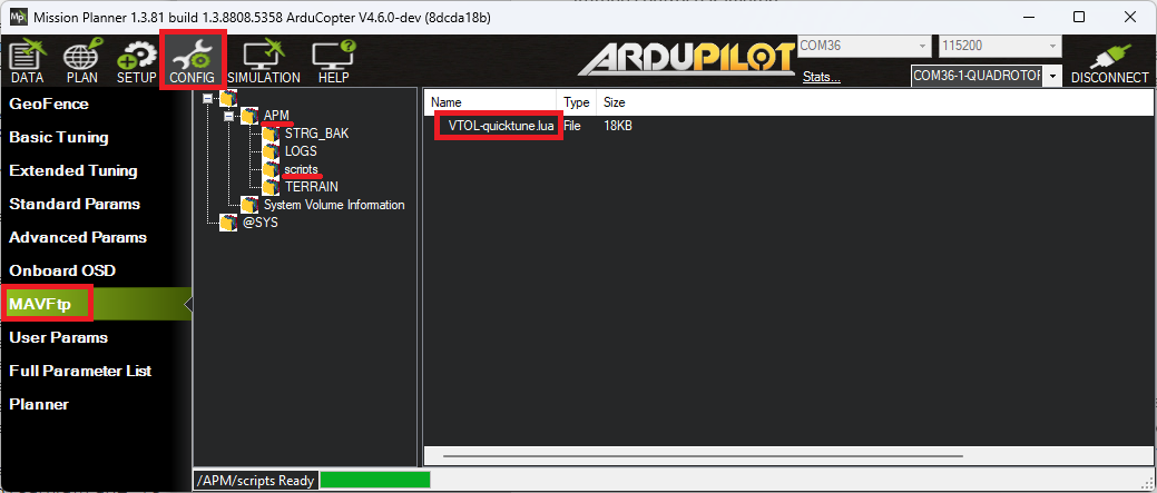
Reboot the autopilot and set QUIK_ENABLE = 1
If an RC switch will be used to start/stop the tune set RCx_OPTION = 300 where "x" is the RC input channel number. Alternatively set one of Mission Planner's Aux Function tab's rows to "Scripting1"
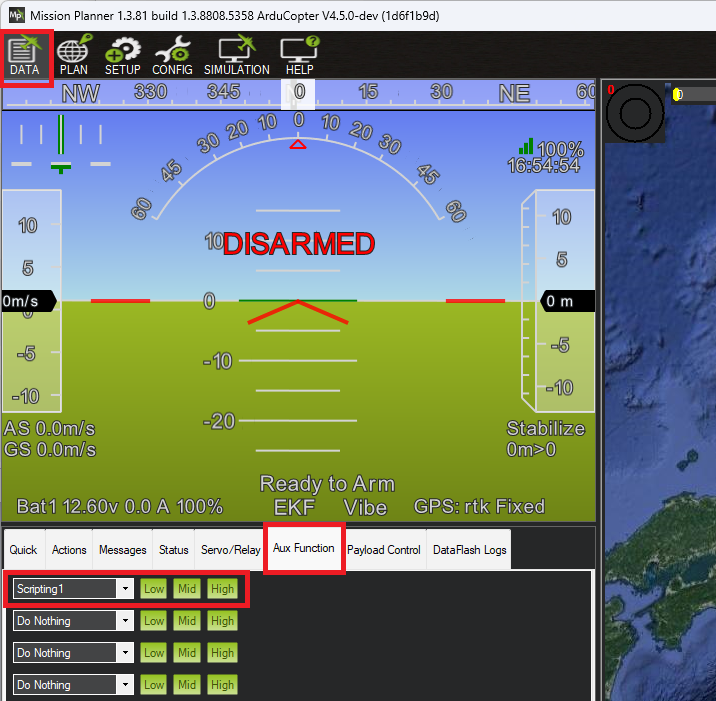


Running QuikTune
- Wait for a calm day and go to an open area with good GPS reception
- Connect with a ground station (e.g Mission Planner or QGC) and ensure that the Messages tab can be seen. This is where output from the tune will appear
- Move the RC switch to the low position OR push MP's Aux Function's "Low" button
- Arm and takeoff in Loiter mode and climb to a height of about 3m
- Begin the tune by moving the RC switch to the middle position OR push MP's Aux Function's "Mid" button
- Monitor the progress of the tune using the GCS's Messages tab
- If necessary reposition the vehicle using the RC transmitter. This will temporarily pause tuning and restore the original gains. Tuning will resume a few seconds after the RC sticks are returned to their center position
- If the vehicle begins oscillating violently cancel the tune by moving the RC switch to the low position OR push MP's Aux Function's "Low" button
- Once the tune has completed accept the new gains by moving the RC aux switch to the high position OR push MP's Aux Function's "High" button
- Land and disarm the vehicle
Advanced Configuration
The full list of available parameter settings are here
【本页后半部分仍为英文原文摘录,补译中。】
译自 ArduPilot Copter「QuikTune」· 查看原文 · CC BY-SA 3.0
roll-pitch-controller-tuning
上游文档:roll-pitch-controller-tuning。
调参前准备
设置起降飞机
下列参数应当根据您的飞机的规格正确设定.。 每一个都影响到调试过程的质量。
电池设置
必须确保你的VTOL的推力 仍旧是线性的仍旧是线性推力曲线的意思 电动机产生的实际推力的变化是直接的 at at at at鲨 at at at at at at at at at at at at at at at at at at 我可不想 at at at at at at at at at at at at at at at at at at at at at at at at at at at at at at at at at. - i at sub鲨? - i - i - i at - i at - i at 曲子不是线性的 那样你就不会韵律好 在某些情况下,你的车可能 会有这么糟糕的曲调 变得完全不稳定和崩溃。
非线性推力曲线共有3个常见原因.
- 节流阀的电压增加
- 您使用到您的 ESC 的 PWM 范围内的端点设置不正确( 见下文“ 移动器设置 ”)
- 由螺旋桨、ESC和电动机组合产生的推力的非线研讨
开始设置电压范围以应对电压sag. 用来线化你的运动推力曲线的参数。
- ** MOT BAT VOLT MAX ** 应设定为电池的最大电压,例如标准LiPos的4.2v x 号电池,或者如果使用不同的电池类型,则酌情设置。
- **MOT BAT VOLT MIN (中文(简体) ). ** 应设定为电池的最小电压,例如标准LiPos的3.3v x 号电池,或者如果使用不同的电池类型,则酌情设定。
- 选择 = 0 (default). The default is to use sag compensated voltage for the above and during tuning computations. It can be set to 1 to use raw voltage instead of sag compensated voltage, which may improve tuning results for light vehicles.
Next setup the thrust expo. If you are setting up a professional aircraft then you should invest in a thrust stand so you can accurately measure the true thrust for your motor/ESC/propeller combination as you vary the throttle. Then you will adjust the expo value along with the endpoints (given by motors setup below) so that the thrust between the endpoints is as linear as possible. Do not trust manufacturer data for the thrust curve as they are frequently inaccurate. See motor-thrust-scaling for details on thrust scaling.
If you are setting up a hobby grade vehicle then you can use the graph below to estimate the correct **MOT_THST_EXPO ** value for your aircraft.
- **MOT_THST_EXPO **: 0.55 for 5 inch props, 0.65 for 10 inch props, 0.75 for 20 inch props (or larger). This parameter should be derived by thrust stand measurements for best results (don’t trust manufacturer data).

警告:
Do not set an expo above 0.75 unless you have thrust stand data for your own motor, ESC and propeller combination showing that a higher value is needed. The graph is an approximation for hobby grade hardware, and guessing at a high expo can make the vehicle harder to tune rather than easier.
Motors setup
The motor parameters define the PWM output range sent to the ESCs. This is critical to ensure that the entire range of throttle values used in flight is within the linear range of your propulsion system.
Parameters used to define the output range sent to the ESC.
- **MOT_PWM_MAX **: Check ESC manual for fixed range or 2000us
- **MOT_PWM_MIN **: Check ESC manual for fixed range or 1000us
- **MOT_SPIN_ARM **: use the **motor test feature ** to determine a value which will reliably start the motors spinning at a low rpm as an indication of the armed state.
- **MOT_SPIN_MAX **: 0.95
- **MOT_SPIN_MIN **: use the **motor test feature ** and motor test data, if available, to set the lower range of linear thrust. The default value is usually adequate for hobby uses.
- **MOT_THST_HOVER **: 0.25 or below the expected actual hover thrust percentage (lower is safe)
PID Controller Initial Setup
The settings below are meant to get your PID controller acceleration and filter settings into the right approximate range for your vehicle. These parameters are critical to the tuning process. The PID controller default values for axis P/D/I values are usually safe for first test hovers of most vehicles.
- **INS_ACCEL_FILTER **: 10Hz
- **INS_GYRO_FILTER **: 80Hz for 5 inch props, 40Hz for 10 inch props, 20Hz for 20 inch props (or larger)
- ATC_ACC_P_MAX: 1100 for 10 inch props, 500 for 20 inch props, 200 for 30 inch props
- ATC_ACC_R_MAX: 1100 for 10 inch props, 500 for 20 inch props, 200 for 30 inch props
- ATC_ACC_Y_MAX: 200 for 10 inch props, 100 for 20 inch props, 90 for 30 inch props
- **ATC_RAT_PIT_FLTD **: **INS_GYRO_FILTER ** / 2
- **ATC_RAT_PIT_FLTT **: **INS_GYRO_FILTER ** / 2
- **ATC_RAT_RLL_FLTD **: **INS_GYRO_FILTER ** / 2
- **ATC_RAT_RLL_FLTT **: **INS_GYRO_FILTER ** / 2
- **ATC_RAT_YAW_FLTE **: 2
- **ATC_RAT_YAW_FLTT **: **INS_GYRO_FILTER ** / 2


Mission Planner Helper
A tab under SETUP/Mandatory Hardware/Initial Parameter Setup is provided in Mission Planner to setup the above parameters easily.

【本页后半部分仍为英文原文摘录,补译中。】
译自 ArduPilot Copter「Setting the Aircraft Up for Tuning」· 查看原文 · CC BY-SA 3.0
tecs-total-energy-control-system-for-speed-height-tuning-guide
上游文档:tecs-total-energy-control-system-for-speed-height-tuning-guide。
油门增益(Throttle Boost)
即便调制良好 多条条条条条条条条条条条条条条条条条条条条条 这将瞬间失去严格的态度控制 突然,巨大的节流阀变化。 dips和Rolls可以在"punch-outs"或"throttle chops"上发生,特别是在推力对重量比较高的轻型机体上.
为了减少这种影响,ATC THR G 组织参数可以调整. 通常以"0"的默认值不活动,设置为非零数,在节流阀迅速聆讯时,会提供PID增益乘法,无论是上下变化. 在那边ATC THR G 组织在节流迅速改变期间,其比子小的比子小的比子小的比子小的比子小的比子小的比子小的比子小的比子小的比子小的比子小的比子小的比子小的比子小的比子小的比子小的比子小的比子小的比子小的比子小的比子小的比子小的比子小的比子小的比子小你怎么快? 数值较低将导致收益乘数较低。
越不严调机体,就越需要Throttle Boost.
【本页后半部分仍为英文原文摘录,补译中。】
译自 ArduPilot Copter「Throttle Boost」· 查看原文 · CC BY-SA 3.0
推力损失与偏航不平衡告警
如果您看到推力丢失或 yaw 不平衡警告, 此页面将列出一些检查和修改, 以解决这个问题 。 在大多数情况下,这些警告是硬件选择或设置不正确的结果。
这些警告旨在检测推进系统中的硬件故障. 如果它们开始出现在未发出警报的飞行器上,则应对推进系统进行核查。 警告更有可能在更大的有效载荷和强风/强风中发生。
的可行性损失
如果在GCS或数据闪存日志中看到潜在的推 就这样,应当进行调查,找出原因和补救办法。 警告会给出一个运动号,例如:
`潜在脉冲损失(3)'
这些警告是马达或马达在百分之百的节流下饱和的结果. 由于这种饱和的ArduCopter无法再实现所要求的卷,投,yaw和节流器输出. 如果这种情况持续很长时间,机体将降低高度和姿态控制,并可能坠毁。
如果在徘徊或放松飞行中橘子看到这些消息,问题必须用硬件固定. 飞行器的推力与重量之比应当通过推进力的改变或质量的降低来提高.
如果只在攀登和攻击性机动中看到,就可能足以降低所要求的加速和速度。 机体的推力与重量之比还可以提高,以允许更高的加速度和速度.
姚错平衡
yaw不平衡警告是衡量机体对yaw有多努力的一个尺度,警告会在yaw输出饱和前触发. 如果yaw输出 饱和机体 维持犹太文化的能力将受到损害。 在最糟糕的情况下,这会导致机体迅速旋转。 警告消息给出最大yaw输出的百分比 。 百分之百饱和 例如:
`Yaw Imball 87 %` %`'
如果在徘徊中看到这个问题,应该用硬件来解决. 如果没有飞行员yaw输入值在增加,机体应立即着陆。 在数据flash日志中,Yaw不平衡可以通过比较对立马达的参数之间的PWM输出来ắn识别. 它将显示顺时针和逆时针马达之间的大节流电位差,如下年鉴所示:

This should be fixed in hardware. The most common cause is the motors not being vertical on a circular arm. If the imbalance still persists the motors can be tilted slightly such that the thrust angle assists the yaw for its rotation direction. Some vehicles can be extremely sensitive to motors thrust vector.
If the warning is only seen in aggressive yaw maneuvers, the warning threshold can be increased by raising ATC_RAT_YAW_IMAX. However, it may also be worth revisiting the yaw tune.
说明:
Both the thrust loss and yaw imbalance warnings can be disabled with the FLIGHT_OPTIONS parameter. This should only be done after extensive log review and testing to verify the warnings are not picking up genuine issues.
【本页后半部分仍为英文原文摘录,补译中。】
译自 ArduPilot Copter「Thrust Loss and Yaw Imbalance Warnings」· 查看原文 · CC BY-SA 3.0
调参流程说明
调制过程包括以下藜类步骤:
- 设定参数,为第一批调试飞行做准备
- **初调飞行**身分,以获得稳定但不一定优化的调.
- ** 初步稳定调制的评价**
- 设置 噪声noch过滤器,参见普通- 最小过滤
- 手动调制卷和皮奇和/或使用qui脚本(在尝试使用AUTOTUNE之前需要) !
- 非洲联盟.
- 设置Input Shaping parameters to obtain the desired "feel"
The initial tune of the aircraft should be done in the aircraft's most agile configuration. This generally means that the aircraft will be at its minimum take off weight with fully charged batteries.
说明:
Following each of the above steps will usually result in a safe tuning process and adequate tune for most users. Alternatively consider using the Methodic Configurator for step-by-step setup
Advanced Tuning
ArduCopter has an extremely flexible controller design that has been used with great results on aircraft from 100g to 500kg. There are a number of difficult control problems that provide a greater depth of understanding that can be provided here. Some of these issues include:
- High gyro noise levels
- Flexible airframes
- Soft vibration dampers
- Large payloads on flexible or loose mounts
- Rate limited actuators
- Non-Linear actuators
- Extremely aggressive or dynamic flight
【本页后半部分仍为英文原文摘录,补译中。】
译自 ArduPilot Copter「Tuning Process Instructions」· 查看原文 · CC BY-SA 3.0