首次设置
地面站、装配、固件、连接
- 飞控系统装配
- 用 Mission Planner 连接飞控
- 飞控接线
- 安装地面站软件
- 烧录固件
- 安装飞控
- 连接电调与电机
- 首次设置
- 自定义固件
- 安装 SD 卡
- 安装 GPS / 罗盘模块
- 向 ChibiOS 板卡烧录固件
- 向 Pixhawk 烧录固件
- 磁干扰
- Navio2 接线与快速开始
- 减振
飞控系统装配
本节载有汇编“基本”的指示。 Pixhawk和其他自动驾驶器上的Cop用以控制 那个 添加其他硬件的指令包含在 ** 备选硬件**。
译自 ArduPilot Copter「Autopilot System Assembly Instructions」· 查看原文 · CC BY-SA 3.0
用 Mission Planner 连接飞控
这篇文章解释了如何连接特派团规划员到自动驾驶器 以便接收遥测和控制机体。
说明:
连接有单独的指令,以便 ** Load Firmware **。
建立连接
要建立连接, 您必须先选择通讯 您想要使用的方法/频道,然后设置物理硬件 和 Windows 设备驱动程序。 您可以使用 USB电缆,**遥测无线电**,**, *蓝牙* IP连接等.
说明:
您的连接硬件驱动程序必须在 Windows 上显示 这使得您连接的 COM 端口和默认数据速率可用 改为特派团规划员.

Pixhawk USB 连接

使用 SiK 无线电连接
打开特派团规划员中,使用 操控屏幕右上角的框。

一旦加入USB或遥测无线电,Windows将 自动指定您的自动驾驶 COM 端口号码, 这将 在下拉菜单中显示(实际数字无关紧要)。 那个 还为连接设置了适当的数据率(通常是USB) 连接数据率为115200,无线电连接率为57600.
长官ộ子连接按钮可以连接到自动驾驶。 连接后特派团规划员将下载自动驾驶器的主持了参数,按钮将更改 改为分解重新审查所示:

提示:
“ 选择端口” 下拉还包含 TCP 或 UDP 端口选项 用于通过网络连接自动驾驶。
端口选择框下的“ Stats...” 热链接如果点击, 将会给出连接信息, 如签名安全 你是谁?正在激活, 链接 STAT 等。 有时这个窗口会浮现到当前屏幕下,需要带到前面才能 总被看到.

连接多辆车
可通过右键单击连接按钮和选择连接选项从下降列表。

预写连接列表的文件可以装入连接列表下拉选项。 这是文件的示例格式 :
tcp://127.0.0.1:5670 (英语).
之间的相互关系
注重工作
序列号:com4:115200
解决问题
如果任务规划员无法连接:
- 检查选定方法是否使用正确的包率 (USB115200或无线电/遥测57600)
- 如果通过 USB 连接, 请确定 后几秒钟的电量已经过后 尝试连接。 如果您在启动器 100 初始化期间尝试连接, Windows 可能会得到错误的 USB 信息 。 在此之后的连接尝试可能要求 USB 连接被解插并重插, 然后等待启动器输入主代码( 几秒), 然后尝试连接 。 有时,如果在启动器初始化期间试图连接,则必须重新启动M所提供的MP。
- 如果在 Windows 上使用 COM 端口, 请检查连接的 COM 端口 存在于Windows设备管理器序列端口列表中。
- 如果您的自动驾驶器有F7或H7处理器,并且有CAN端口,那么请参见下面的一节,**Troubleschoolsing 复合连接**
- 如果使用 USB 端口, 请尝试不同的物理 USB 端口
- 如果使用 UDP 或 TCP 连接, 请检查您的防火墙是否没有屏蔽 IP 流量
您还应确保自动驾驶控制板 安装了适当的ArduPilot固件,并已正确启动(在 皮克斯鹰有有用的**LED**和 ** 听起来可以告诉你自动驾驶的状态。
如果使用远程链接(不是USB)和Mission Planner连接,但不下载参数,或者无法像模式更改一样获得命令,那么自动驾驶器很可能已经打开了签名. 见常见的 MAVLink2 签名.
解决复合连接的难题
拥有F7或H7处理器且拥有CAN接口的自动驾驶员使用显示两个USB接口的固件:一个用于正常的MAVLink连接,另一个用于SLCAN序列连接到CAN接口,用于配置和固件更新. 这被称为复合USB设备.
默认情况下,MAVLink USB接口是SERIAL0,SLCAN USB接口是棋盘呈现的最高SERI 给我端口. 目前安装在 Mission Planner 的 Windows 驱动程序可以选择使用其中之一,由于两者默认都设置在 MAVLINK 协议的ArduPilot 固件中,因此无论它选择哪一个作为COM端口,它都会很好使用.
然而,存在一种情况,即用户会发现它不会连接到任务规划箱中显而易见的COM端口. 当用户实际上是将Windows驱动程序作为问题以及 MAVL侬 COM 端口使用的任意 SERIALx 端口的协议不慎更改为 MAVLink 之外的东西时,就会发生这种情况. 如果用户从使用不同自动驾驶器的机体配置中获取一个已有的参数文件,并且协议已经更改,这种情况就很容易发生. 例如,用户拥有一个非F7/H7CAN能另外一些自动驾驶的平面,并将其升级到一个即,然后在安装新自动驾驶的平面的同时加载他现有的参数文件. 一旦参数文件被加载,自动驾驶器被重启,通信就会丢失,无法重建.
所发生的是,Windows使用的SERIALx端口的协议已经更改. 几乎总是,这是SERIALx端口的最高编号,因为这个端口在非CAN能力自动驾驶上通常被设定为-1,Windows COM端口驱动程序选择了这个接口作为COM端口而不是SERIAL0.
追回程序如下:
- 转到Windows设备管理器,在Ports列表中找到自动驾驶员正在使用的COM端口. 它将拥有COM Port #不间断地连接到最初的Mission Planner. 右键点击后, 它将呈现“ Update 驱动程序软件” 作为选项之一 。 点击它。

- 我们得点击“浏览我的计算机...” 选项,然后点击“从列表中选择...”选项,你可以看到这个屏幕:

- 从"从"从"从"从"从"从"从"从"从"从"从"从"从"从"从"从"从"从"到"从"从"从"从"到"从"从"从"从"从"从"到"从"从"到"从"从"到"从"从"到"从"到"从"到"从"从"到 是呀从"从"从"到"到"从"到"从"到"到"从"到"到"到"从"到"到"到",从"从"从"到"到"到"到",从"到"到",从"到"到"到"),从"从"到","从"到"到",","从","从",",",",",",",",",",",",",",",",",",",",",",",",",",",",",",",",",",
- 现在将您的自动驾驶器重新连接到 PC 和两个 COM 端口将呈现。 一个将连接(剩下的一个与MAVLink协议连接),另一个将不连接. 如果您不连接到一个, 请尝试另一个 。 但不要把自动驾驶从个人电脑上断开 否则复合驱动器会卸下,你必须重新开始。
- 现在您已连接到任务规划器, 请将序列号端口协议的协议 更改为 2 ( MAVLink2) 。 您现在可以断开并重新连接自动驾驶器, 它将只显示一个COM端口, 如果你不从现在开始就可以连接。 除非尝试使用 SLCAN 接口, 从现在起不要更改此协议 。 由于正在使用的Mission Planner SERIALx端口已不再是正常的SERIAL0,而是最高端口,因此可能有点陌生,但这不影响自动驾驶器的配置和操作.
相关专题
**任务规划员蓝牙连接
[copywiki 目的地="飞机,直升机,rover,planner,sub,blimp"].
译自 ArduPilot Copter「Connect Mission Planner to AutoPilot」· 查看原文 · CC BY-SA 3.0
飞控接线
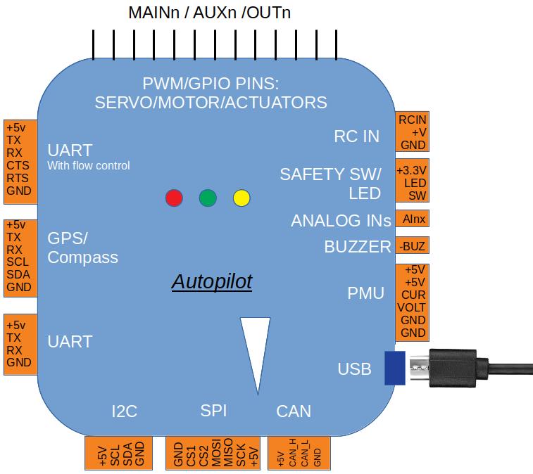
这一主题涉及基本/强制性外围线与自动驾驶的接线/连接。 关于每个自动驾驶端口/连接器的详细解释,见通用飞行控制器
全球定位系统/计算机辅助系统
GPS通常在飞机、巡逻车和越野车中是强制性的,除非其他某些位置确定**. 潜艇不使用全球定位系统。 Copter、Rover、Sub和QuadPlane等类型的Plane通常也需要指南针(见** common-companyless)。不过,建议采用指南针替代品,而不是常规计划。
说明:
一些Copter和Rover模式可以在没有GPS和Compass的情况下运行(参见其飞行模式的机体文件).
系统中可使用多种全球定位系统和/或合成系统,见常数gps- 混合, 常见的组合,以及普通- ek3- 外率更多信息
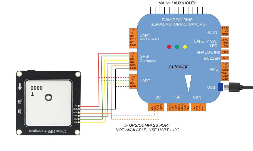
说明:
TX和RX从自动驾驶器交换到GPS模块.
说明:
通常GPS默认会附在ArduPilot的逻辑序列端口3上. 然而,自动驾驶上的ArduPilot的系列Port 3上哪些物理的UART被分配到自动驾驶上的Serial Port 3,在自动驾驶**文件**中记录.
说明:
重要的是,GPS应连接到第一个拥有SERIALx端口的SERIALx端口。缩略语 PROTOCOL参数设置为“ 5”( GPS) , 因为如果在配置为 GPS 协议的第一个端口上找不到的话, 在启动时将停止搜索 GPS 婶婶。
作为线条示例,主题**3DR UBlox GPS + Compass Module ** 显示如何连接到一个Pixhawk自动驾驶器,并包含额外的配置据以加载的信息在其任务范围内.
驻地协调员的投入
说明:
分公司目前不使用驻地协调员控制,但正在制定中。
无线电控制接收器通常用于飞行员控制. 虽然可以使用遥测技术通过地面站进行独家试点控制,但建议不予采纳。 (然而,通过地面站软件可以使用滑翔杆控制机体. 见**Joysticks**。
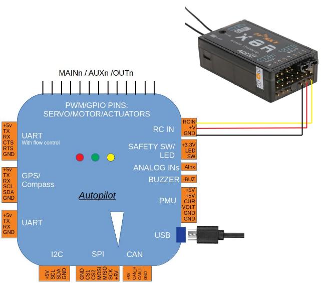
ArduPilot 自动检测以下RC接收程序协议:
- 你想看看吗?
- SBus 接收器
- FPort 接收器( 参见普通-F端口接收器 )
- 交火(CRSF)和ELRS接收器(见共通点弧,需要全UART连接. )
- Spektrum DSM和DSM2接收器
- Spektrum DSM-X卫星接收器
- IBUS 接收器
- MULTIPLEX SRXL版本1和版本2接收器.
传统单线每通道接收器的PPM编码器 可用于将接收器输出转换为 PPM。
提示:
至ArduPilot 4.0版本的固件,任何自动驾驶的UART都可以作为RC接收器的输入,而不是指定的RCin或S 目录的输入针,设置该端口的缩略语 PROTOCOL到23号 然而,一些串行协议要求倒置(SBUS,FPort),UART必须能够使用.语录( O)要反转 RX 输入的参数, 否则需要外部反转器 。 这也允许将第二个RC接收器附在自动驾驶器上进行冗余. 如果第一个接收器(在启动后第一个检测到有效)失败,那么第二个将使用. 请注意,任何RC输入范围及修饰的校准,在开始使用时,将用于第二个区域。 两台接收器都设置为不发送脉冲的故障 快走RC 选项bit 10 也必须设置。
提示:
关于兼容的接收器及其连接方式的信息可见于共用弧形系统。另见普通- 多分子- rx使用多个驻地协调员接收器

FRSKY 塔拉尼斯传输器
汽车/Servo连接
汽车ESC和/或PWM 是否会附在自动驾驶充分落实的PWM输出上.
它们被贴上MAIN/AUX输出的标签,或者被贴上OUPU蜕变的标签. 这些输出为发动机ESC或飞行表面的伺服器提供PWM或Dshot信号. 它们有时也可以作为通用的I/O披针用于控制继电器,降落伞,抓手等.
带有MAIN/AUX输出标签的控制器通常表示正在使用化管方案联合处理器。对发展而言,这些产出 现在是作为发动机/服务器输出的,如果主自动驾驶失败,则为落实RC提供多余的控制供其使用。 Main 输出来自此共处理器,而A蚂蚁X指定输出则直接从自动驾驶器控制. 大多数棋盘级自动驾驶器不使用IOMCU,输出时只标注OUPUTx或Mx.
这种区分很重要,因为AUX输出 请使用AUX输出(和AUPUT来自没有ICPU的自动驾驶)以及PWM或Dshot。 虽然主要产出只能用于PWM.
说明:
一些不使用IOMCU标记其输出为MaIN的自动驾驶器,因此实际上具有GPIOs和/或DshotESC控制输出的能力. CUAV V5 Nano和Holybro Pixhawk 4 Mini都是例子.
除了个别输出信号之外,这些输出往往在供应或分配伺服器功率和地面的3个披针连接条上提供。 这种功率通常由外部提供,例如由ESC或BEC提供,虽然有些自动驾驶员从内部监管者那里提供这种功率.
Rover 的连接示例

仅使用马达的ĩ主 在这种情况下,只有ESC信号ĩ影线被连接.

[站点维基="copter"]. 关于科普特,另见**连锁ESC和汽车**。
总而言之对实现从PDB连接到PDB的每条信号线来说, 主输出信号(S) 针按运动编号:
- 产出1 = 汽车1 - - 产出5 = 汽车5
- 产出2 = 汽车2 - - 产出6 = 汽车6
- 产出3 = 汽车3 - - 产出7 = 汽车7
- 产出4 = 汽车4 - - 产出8 = 汽车8
[/现场]
[站点维基="飞机"]. 对于飞机将控制通道线与主输出信号连接起来 针 :
- 产出1=Aileron
- 产出2=电梯
- 产出3=喉咙
- 产出4=舵手
[/现场]
[站点维基="rover"]. 对于 Rovers 将油门和导线连接到主输出 信号针。 默认设置为:
- 产出3=喉咙
- 产出1=指导
滑动-滑动输出函数参数用于配置具有有固定轮子 你很像油箱轨轨的机体(即不使用伺服器来引导轮子,而是使用左右轮之间的差速). 用于每边电动机的输出的 SERVOx F功能设定使用左旋转和右转输出函数。 见漫游汽车功能**
[/现场]
[站点维基="sub"].
** 正在编写次级连接指南。[/现场]
连接蜂鸣器和安全开关
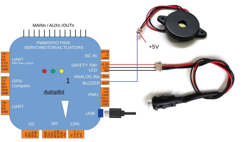
蜂鸣器和安全开关按钮是可选的,但对某些配置有用. 并非所有的自动驾驶都提供这些连接. 如所示,一个BUZZER和SWITCH可连接到各自的港口。
警告:
呼叫机离飞机至少5厘米 控制器或噪声可能会使加速计不适.
连接其他外围
取决于您的硬件 可能还有其它的外围 包括传感器、摄像头、钳子等。 这些可以找到 ** 备选硬件**。
有关这些外围连接到自动驾驶的信息,请访问 这两页。
有关资料
- [网站维使它们能够="copter"谐音].
- 高级皮克斯霍克Quadcopter 线程图 < 高级皮克斯霍克- Quadcopter- 线程图 >
[/现场]
译自 ArduPilot Copter「Typical Autopilot Wiring Connections」· 查看原文 · CC BY-SA 3.0
安装地面站软件
ArduPilot可与**多个不同的地面站使用**.
开发者通常使用a桌面GCS,因为它们往往能提供更深入的机体设置参数和先进的调试功能. 如果您只是想飞行,您可以选择使用移动OS运行的GCS(iOS,Android).
为一些更流行的GCS系统提供的安装链接如下:
**任务规划员**(温道、Linux、Android):** 安装任务规划员** 这个GCS是ArduPilot中最兼容和最紧密地跟踪新的特性和更新. 推荐给首次用户和电力用户。 它在Windows环境中的功能最好.
回合控制(Windows,Mac OS X,Linux,Android和iOS). 这是Android系统最受欢迎的GCS,为手机等小型格式设备提供了最好的演示. 不具备特派团规划员的所有能力,但有些职能的接口更方便用户。 在所有平台上运行良好
**APM Planner 2 ** (Windows, Mac OS X, L坛x): ** Install APM Planner 2 ** - 提供基本功能,但目前维护和更新不完善.
阿尔杜迪克(Windows, mac OS X, Linux): (中文(简体) ).目前在Alpha测试中 - 反馈欢迎!一个免费,开源的地面站,用现代化的UI建造. 支持实时与否遥测,任务规划与地形意识高度剖面,全参数管理,校准向导,固件闪烁,视觉Lua脚本编辑器,以及MAVLink签名. 同时通过MSP协议支持BetaFlight和iNav.
[copywiki 目的地="copter,plane,rover,sub,blimp"].
译自 ArduPilot Copter「Installing Ground Station (GCS) software」· 查看原文 · CC BY-SA 3.0
烧录固件
[copywiki 目的地='copter,plane,rover,planner,blimp,sub'].
装入固件
本页面解释如何让ArduPilot固件进入自动驾驶器:如何分辨已经放在棋盘上的东西,因此需要哪种加载方法,以及如何确认结果.
提示:
如果你的自动驾驶员已经运行了ArduPilot,而你只是想更新到新的版本,你可以直接跳转到其下, 其下, 并存于下, 其下, 并存于下, 并存于下, 并存于下, 并存于下..
步骤1:将自动驾驶器连接到计算机
** 在你的计算机上安装一个地面站**,然后用USB电缆连接自动驾驶。 直接在计算机上使用USB端口,而不是USB中枢.
Pixhawk USB 连接
对于这第一步,插入板子通常: do没有扣上DFU/BOOT按钮,不要连接BOOT针. 下一步要看董事会在自己开始的时候如何表现自己.
Windows应当自动检测并安装正确的驱动软件.
说明:
如果下一步一无所获 就怀疑有线 操控板 许多使用消费朔方电子设备销售的USB电缆都是充电 một数据线.
步骤2:检查 自动驾驶器上已经包含的内容
ArduPilot固件是由一个长期联合国系统自动驾驶员闪存的小型程序所装入的,称为“卸载器”。 ArduPilot自己的装货机和它从下来的PX4装货机鳏夫,都正在为USB上空的地面站接受固件. 属于其他固件的bootloaders,如大多数Beta Albalight飞行控制器上运来的机型,没有,必须在ArduPilot首次装入之前更换.
如果自动驾驶器是从一个ArduPilot 合作伙伴,或者它以前运行过ArduPilot或PX4固件。 这是正常的没有显示运行 Betaflight、 INAV 或类似的棋盘圆满完成, 或者棋盘的页面在通用自动驾驶器说ArduPilot必须第一次通过DFU加载.
如果你不确定,看看板 如何在计算机上出现 它插上如上。
你找到的东西意味着:
- 存在一个ArduPilot 兼容的启动器如果棋盘显示为以自动驾驶器命名的串行设备,即:
立方体Orange+ 变形器或皮克斯霍克6C。同名词与- 比尔或- 保证BL -v10安全附录表示棋盘目前坐落在ArduPilot bootloader,而不是主固件中,这也很好,尽管并不是每个棋盘都会在bootloader中更改名称. 主要 PX4 时代板PX4 传真机或PX4 BL FMU 软件作为最后确认,特派团规划员SETUP 安装固件屏幕会检测板。 - 不存在ArduPilot 兼容的启动器如果序列设备被命名为其他固件,即:
Được rồi.,INAV 互联网档案馆,或通用软件STM可能成为虚拟连线,或者如果棋盘仅作为 DFU 设备可见,在握住 DFU/BOOT 按钮后出现,或者在插入时连接 BOOT 针头.
第3步:装入固件
如果存在兼容的 ArduPilot 启动器后续其下, 其下, 并存于下, 其下, 并存于下, 并存于下, 并存于下, 并存于下.地面站将固件安装在 USB 连接上 这也是以后每个固件更新所使用的方法.
如果不是的话后续普通装填器件 -- -- 软件 -- -- 仅限芯片。ArduPilot 启动器和固件作为单一文件下载,并使用STM32CubeProgrammer在DFU模式的USB上加载。 这是一个一次性的操作:一旦它成功,板子就有一个ArduPilot bootload器,后来的所有更新都使用上面的地面站方法. 该页还覆盖了来自外部闪存的板块,例如SPRacing系列,它们再次需要不同的程序.
说明:
一些带有1MB闪存担当的自动驾驶员 难道为了保存闪存空间,没有在他们的固件中包含一个装入器的复制件. 这些板安装了兼容的卸载器,但无法从ArduPilot内部更新;见普通加载器更新.
第4步:测试是否奏效
固件装入后:
- 上传完成后等待几秒钟。 通常要花一点时间,靴装机才能退出并启动主固件,然后在此之前连接就会失败.
- 新闻连接在你们的地面站。 ** 连接任务规划员到自动助理** 有更多信息。
- 证实有关连接的固件版本和机体类型。 在任务规划中,信件选项卡,在HUD, 作为自动驾驶靴。
- 切换到飞行任务规划员飞行数据屏幕和倾斜板。 团结与民主联盟的态度应该遵循,这证实了该固件正在运行和阅读IMU。
此时任何枪前信息都需在新装的自动驾驶上:机体仍需要其**加速计**,**compass **,以及**radio **校准才能武装.
补充资料
正在下载固件
地面站,例如特派团规划员下载和安装稳定因此,需要手动下载的软件贝塔,开发,或自定义构建,或当自动驾驶需要DFU加载时.
每个支持的自动驾驶的固件都会在ArduPilot 固件服务器要找到正确的文件 :
- 打开(原始内容存档于2018-07-21). Stirtyware.ardupilot.org
- 单击机体类型的链接(即:飞机, 计算机, 罗弗, 次级或天线跟踪器)
- 选择您想要的释放 :
稳定,贝塔,或最新数据(见下文各节) - 查找名称与您的自动驾驶最匹配的目录
- 下载适合您将使用的加载方法的文件 :
页:1- 单是坚固器件,通过地面站装入已经装有ArduPilot兼容的装货机的板上使用 bl.hex 的参数- 装货机和固件结合,通过DFU装入没有ArduPilot兼容装货机的板上阿尔杜XXX.abin- 从SD卡装上**,在支持它的自动驾驶机上阿尔杜XXX.bin- 原始二进制,用于dfu-util (法语)和来自外部闪光板的
说明:
一些自动驾驶器针对的是特定机体类型,而固件并不是自动为其他机体制造的. 仍然可以为这些机体建造ArduPilot,自定义固件构建服务器.
稳定
稳定是当前发布的,并且是几乎所有人的正确选择。 这是有助于提高地面站安装的 默认从其固件安装屏幕。 每辆车稳定目录总是保存最新版本;过去的特定版本保留在编号中稳定-x.y.z旁边有目录
说明:
ArduPilot计划非常谨慎,玲珑一世的任何事物要么被评价为公正地限制了它对现有系统 往后的影响,要么 你还好吗? 我们鼓励用户升级到任何发布的点发布,因为他们有时包含非常重要的bugfixs.
贝塔
在此之前展开了稳定释放,贝塔版本发布. 如果您想要尝试更新的特性或帮助开发者测试新的代码,这些代码可能会被使用. 由于这些是"β"版本,可能仍然存在bugs. 即使在稳定释放固件中也有可能。 然而,一个Beta发行版已经开发团队测试了,并且已经进行了飞行测试. 此发布允许更广泛的用户群在发布前完成固件测试 。稳定。鼓励有经验的ArduPilot用户测试这一固件并反馈。
任务规划员对我给你安装固件上传此发行的页面, 但稍后稳定释放可能已经存在。 请先检查普通机体上传选项 。
最新开发者版本
这反映了ArduPilot代码开发分支的现状. 开发小组已对其进行审查,通过了所有自动化测试套房,在大多数情况下还进行了测试 看,这些测试套房都已经通过。 此代码每天构建,可供有经验的用户测试. 这相当于"alpha"的释放,并且可能存在bugs,尽管很少出现"crash approduction". 在添加了修改或引入了 49 个功能之后不久, 维基语录中的 **Upcoming features ** 部分更新了添加或更改的信息。
此代码必须手动下载于固件下载页面为最新数据然后使用您的地面站的定制固件选项, 或者通过 DFU 上传。
自定义构建
该自定义固件构建服务器以您选择的特性集构建固件稳定, 贝塔,或最新数据树枝。 这就是如何启用释放的用于闪存限制自动驾驶的固件中没有的特性,而牺牲你不需要的特性. 见通用软件说明,和** 软件特性限制**
参数转换
将固件更新到较新的版本不会改变现有的参数,除非固件是针对对全球不同机体类型的,在这种情况下,参数可有助于对该机体的默认值重 至于该机体的默认值.
升级时,您应当带一份参数,并保存与您正在移动的版本对应的文件名(使用任务规划器上的“保存到文件”按钮)你在清 清 清 清 作为一种 清 清 清 清 清 清 清 清 清 清 清 清可在 清 清 清 清 清 清 清 清 清 清 清 清 清 清 清 清 清 清 清 清 清 清 清 清 清 清 清 清 清 清 清 清 清 清 清 清 清 清 清 清 清 清 清 清 清 清 清 清 清 清 清 清 清 清 清 清 清 清 清 清 清 清 清 清 清 清 清 清 清 清 清 清 清 清 清 清 清 清 清 tai 清 ahead 清清 清 清 清 清 清 清 清 清 清 清 清 清 清 清 清 清 清 清 清 清 清 清 减轻贫穷 如果你决定你必须回到一个更早的固件 这些对修复你的车来说是宝贵的 不过减轻贫穷秘书处的说明曾经将那些保存的参数文件应用到较新版本的固件 sureware!
ArduPilot 努力使固件升级无缝. 有时我们需要移动参数,改变它们的缩放或简单地去掉它们。 固件更新后,我们自动在第一个靴子上进行。
我们不能永远保留这个参数的迁移代码,所以我们保证从哪个版本升级到哪个版本是有限度的. 您仍然可以从旧版本升级到较新的版本,但您可能会发现,在您现在使用默认参数值而不是您自定义的值时,一些功能发生了意想不到的变化.
如果你的自动驾驶器远远落后于现代鹫峰版本,你仍然可以得到参数转换——你只需要闪烁中间版本——使它成为一个多步骤的过程.
| 新版本 | 最旧的迁移版本 |
|---|---|
| 4.8(最新数据) | 4.3 |
| 4.7 | 4.2 |
| 4.6 | 4.1 |
| 4.5 | 4.1 |
| 4.4 | 4.1 |
注意并非每个车型都有每个版本号的发布——例如,Sub没有4.2,4.3,4.4或4.6的发布. 使用您车型领先的版本, 它不比上表中的版本年久; 4.1上的子用户会移动到4.5, 然后移动到4.7 mà.
通过SD卡加裝固 没問題 看来
一些自动驾驶器上的固件可以通过复制一个(原始内容存档于2017-09-29). ardupilot.abin固件文件在SD卡上,然后电源循环ظار الكر 23. 如果USB端口不易进入,或必须远程交付更新,则这样做是有用的联合国宪章。 关于如何通过SD Card更新固件的详情,请参见此处**.
固件特性限制
并不是每个自动驾驶员的固件都包含每个ArduPilot特性. 你很擅长使用1MB闪存的自动驾驶器,特别是其特性被移除,以便符合密码ử.
- 关于以下特征的清单:没有包含在当前“ 最新” 自动驾驶器的固件中,参见此页面。特定板和固件版本的确定列表是:
特性.txt文件夹中的文件固件服务器。见普通有限显现的软件包括记录和档案管理限制。 - 默认从1MB自动驾驶器中排除的每个功能都可以在机上选择.自定义固件构建服务器。许多特征已经您的应用程序可能不需要默认包含, 因此一个自定义构建可以添加一些被排除的特性, 同时又会丢弃一些不需要的特性 。 例如,省略 QuadPlane 支持就可以在不需要的 Plane 上腾出空间。 驱动器和外围支持可以单独选择,以便只有实际使用的驱动器和外围支持能够进行闪存.
- 自定义构建服务器可以从日主分支,以及Stable和Beta分支构建.
译自 ArduPilot Copter「Loading Firmware」· 查看原文 · CC BY-SA 3.0
安装飞控
这篇文章解释了如何按标准挂载自动驾驶器和 备选方向。
我们在标准方向
** 自动驾驶** (Pixhawk等) 应该是 存放在(包括气压计上的泡沫)内,并应 由直接指向前方的白色箭头搭载 车。
它应放在靠近机体重心的地方(两者均位于 横向和纵向)。 一般来说,这意味着应该放在 在佑星车体中间几厘米内, 是否可以使用马达。 是否可以完全放在中间并不重要,但 更接近的情况(没有记录的由艾滋病引起的问题) 控制器远离重心。 如果自动驾驶不能放在机体中心设置**IMU位置抵消参数**,则可能略微提高性能.
[站点维基="rover"]. .图像:././././图像/挂载-飞行控制器-翻车.png
目标 : ./ 图像/挂载-飞行控制器-rover.png
[/现场]
应使用4个震动立方体将板固定在框架上 减少泡沫约3/4英寸平方英寸(3M泡沫可从mrobotics (英语).).

提示:
振荡抑制泡沫是一种简单而有效的机制。 振动控制。 如果 ** 测量振动 ** 显示它不是 有关替代机制的论述,见** " 振动大坝这方面的工作 " **。
备选方向
如果自动驾驶的标准方向不方便,则
可以安装在30多个其他可能的方向。 完整名单
可通过特派团规划员看到和确定可能的方向配置/图宁 高级参数屏幕,查找董事会指导(AHRS OINATION)参数。
对于滚动值,正值表示右滚动(即"Roll90"表示板是). 右转90度,白箭头仍向前点 97. 董事会站在它的 为什么?
对于 Pẫn 值,正数表示回投(即“ Pitch90 ” ) 就是说板子的鼻孔是90度的 所以箭点 直接上楼)
对于Yaw 值,正展开了数字有此表示: 顺时厉旋转(即“ Yaw90” 表示棋盘旋转如此白箭头) ),指向右边.

警告:
如果板子安装在非标准方向上(即箭头没有向前指向报告中的建议),那么请确保A. 人权组织在进行加速度计校准前适当设置。
译自 ArduPilot Copter「Mounting the Autopilot」· 查看原文 · CC BY-SA 3.0
连接电调与电机
这篇文章解释了如何 不知道将ESC,马达和螺旋桨与自动驾驶机连接起来. Pixhawk作为例子使用,但其他自动驾驶器也有类似的连接方式.
连接每个ESC媲美的电源(+)、地面(-)和信号线(s) 自动驾驶的主输出针 按彗星号。 查找框架类型 下面用于确定马达的指定顺序。

Pixhawk 输出针( 那里是数字). 前4个钉子是连接四方的 那里有颜色编码
汽车订单图
下面的图显示了每个帧类型的运动顺序. 推进器方向以绿色(顺时针,CW)或蓝色( 西安)显示. 以红色显示的字母表示在使用Mission Planner时该转动哪个发动机汽车测试特性在其 SETUP - > 备选硬件标签中找到。 该死的, Name

运动顺序图的图例
QU Anh:
说明:
四方Aضر and and and frames frames frames 悼 frames frames frames frames frames frames frames 殆 not Q Q Q Q Q Q Q Centre the Q Q Q Q Q Q茁 Q Q NY Q Q Q Q Q Q Q motor Q motor Q Q Q Q Q Q Q motor Q Q Q Q Q motor motor将性别观点纳入 ya control control control control control motor motor Q Q Q Q Q Q Q Q Q motor motor Q motor motor motor motor Q motor Q Q motor motor motor motor Q Q motor motor Q motor motor motor Q Q Q Q Q Q Q Q Q Q Q Q Q Q Q Q Q Q Q Q Q Q Q Q Q Q Q 运动旋转的方向对基本操作来说并不关键,但除非前马达向相反方向旋转,滚转和投球输入会导致不利的 ya,导致 ya控的动态范围较小.
说明:
四方“ 无Yaw Torque”(NYT)框架主要用于VTOL 缩写器具有大控制表面的配置。 汽车旋转方向对于这些马达无关紧要,但除非马达的旋转方向被设定为任何一种普通的QUAD框架,滚和投球输入将会导致不利的 ya,导致固定翼控制表面的 ya控制的动态范围较小.
黑社会
OCTO 恐惧
渥太华
Y6 恐惧
特里塞 没错 特里塞特
说明:
由于尾部(或鼻)组织合作器用于yaw控制,Tricopter电动机旋转方向对基本操作并不关键,但除非前置电动机向相反方向旋转,滚转和投球输入会导致负的yaw,导致yaw控制动态范围较小. 如果你的尾巴(或鼻子)伺服器的方向 向错误的方向应对yaw,那么要么RCn 永远RC 输入方向或倾斜服务器永远参数应设置为1(从0),详情见**TriCopter设置页**。
细菌
说明:
如果需要,双模马达可逆指示方向旋转(如CW左,CCW右).
多德卡・赫夏夫人
DECA 恐惧
自定义框架
使用最多12个电动机可以配置自定义帧类型, , , 你是不是 , , , , , , , 拌 咱们 兢 开展的 均属 茹 。每个马达的卷、投子和yaw因子必须用脚本计算和装入。 通过设置 **FRAME CLASS ** 至 15 - 脚本矩阵来启用。 见:加四进例和过失容忍十六进制例.
说明:
并非所有自动驾驶员都支持脚本,参见:**wardware限制**.
顺时针识别和逆时针识别螺旋桨
上图的上图,显示有2个型次,即:不得不得时,不得时,不得得, 至少不得不得得,不得得,不得不得 许多. . . . . . . . . . . . . . . . . . . . . . . . . . . 不得. . . . . . 不得. . . 的. . 不得. . . 积极合作. . . .. . . . . . 的. ..... 的........ 的..............的..........的..........的................的....的...的 还好....励怯............的.......... 以的一个基本形状识别正确螺旋桨型的最可靠者如下所示. 较厚的边缘是向旋转方向移动的领先边缘。 后缘较激进的扇贝,通常较薄.
测试电动机旋转方向
如果你完成了**电台** 和**ESC校准**, 你可以检查你的 发动机在向修正方向旋转:
确保你的直升机上没有螺旋桨!
打开发射机并确保飞行模式开关设置为 稳住
连接电池。
举起油门,右转舵 秒数。
讨论会上, 发动机不会旋转,它可能已经失败了前臂安全 检查。
- 枪前安全检查失败也表现在红臂上 轻度双闪,然后重复。
- 如果特别是那些预 Arm 检查失败到 ** 预 Arm 安全不过是检查页 ** 并纠正问题或禁用 继续前的检查。
当你能成功武装时,应用少量节流阀, 3 、 3 、 、 妈 、 、 、 、 、 、 、 、 、 、 、 、 、 、 、 、 、 、 、 、 、 、 、 、 、 、 、 、 、 、 、 、 、 、 、 、 、 、 、 、 、 、 、 、 、 、、 、 、 、 、 、 、 、 、 、 、 、 各国 、 、 、 、 、 、 、 、 、 、 、 、 、 、 、 、 、 、 、 、 、 、 、 、 、 、 、 、 、 、 、 、 、 、 、 、 、 、 、 、 、 、 、 、 、 、 、 、 、 、 、 、 、 、 、 、 、 、 、 、 、 、 、 人 人 人 人 人 妈 人 人 人 人 人 人 人 家 人 人 人 人 人 人 人 人 人 人 人 人 人 人 人 人 人 人 人 人 人 人 人 人 人 人 人 人 人 人 人 人 人 人 人 人 人 人 人 人 人 人 人 人 人 人 人 人 人 人 各国 人 人 人 人 人 人 人 人 人 、 人 人 人 人 人 人 人 家 、 人 人 家 人 人 人 人 人 人 人 人 人 、 人 、 人 人 家 人 家 、 人 人 、 家 、 、 、 人 人 、 、 、 家 、 、 、 人 、 人 、 、 家 、 上面图像中显示的方向,用于您选择的框架 。
扭转任何旋转方向的发动机
提示:
- 移动方向被反转,只是通过 互换两个
三个ESC呼叫电动机
检查机车编号与任务计划机车测试
另一种方式是检查发动机是否已经上钩 正确的是,在任务规划 我没做错 设置菜单 。

任务规划员:汽车测试
通过MAVLink连接到机体时,汪精卫可以点击绿色 按钮和相应的电动机应旋转为 5 秒数。 如示例所示,字母对应的运动编号 见下文。
- 先脱掉你的道具!
- 如果没有马达转动,则将"Throttle%"提升至10%,再试一次. 若为 没用的,试试15%
第一个旋转的电动机 将直接位于前方 + 配置的大小写,或直径右侧的第一个马达 在 X 配置时转发。 然后进行电动机测试 顺时针旋转。

在X8的情况下,它首先会旋转前右上方的电动机,然后 右下方,沿着同样的模式走
OctoV将先旋转前右电动机,然后再次继续 顺时针,直到到达前 他妈的左引擎。
使用配电板

连接运动输出有两种方法. 或连接 电子速度控制器(ESCs)直接到自动驾驶OR使用电源分配板(PDB).
使用 PDB 时,连接电源( +)、 地面( -) 和信号( s) 每个ESC的电线按照运动编号到PDB. 找到你的画框 类型,以确定马达的指定顺序。 然后连接 从PDB到主输出信号针的信号线 自动驾驶(确保电动机订单号与 控制器上的主输出针号). 如果你在用电 模块,将电源和地面电线连接到 PDB 到自动驾驶板. 如果你想用这些 电源舱外或电源舱外的电缆 低电流服务器的点,将地面(-)线连接到主线 输出可能成为主输出功率(+)的电线。
KDE( 和其他) Opto 孤立ESCs
KDEXF- UAS 和 KDEF- UASHV 系列是可视化的, 不提供 外围设备的BEC电源输出. 他们需要+5V来掌权 光线隔离器,而皮克斯鹰可以由伺服器提供动力 铁路,它不为服务铁路提供+5V. ESC必须是 由BEC提供动力,或者依旧在板子上团结起来使用未使用连接器的跳动器. 强烈建议你用BEC来为铁路供电 比跳伞更厉害

KDE ESC 已固定 PWM 范围, 因此您必须手动设定输出 每个PWM信号的射程,使 RCx MIN 太 1100,RCx MAX 是 1900us 使用 计划员
Pixhawk ESC问题
据报道,一些ESC没有与皮克斯霍克合作.
Pixhawk应该和每家ESC合作 一个正常的RC 接收器(因为它发出相同的提交其信号类型)一个已知的例外,EMAX ESC.
在大多数情况下,问题是由于线路不正确。 总是连接信号和地面。 检查采用一种 ESC 类型来决定如何连接 +5V 线条 。 在国家,你必须连接信号和信号地面,以使ESC工作。
更多信息见这段视频.
译自 ArduPilot Copter「Connect ESCs and Motors」· 查看原文 · CC BY-SA 3.0
首次设置

首次设置包括:安装地面站(GCS)、将飞控安装到机架、连接接收机/电源/电机,以及完成初始配置与校准。
说明:本节假定你已选好并组装机架,并已选定飞控型号。
步骤概览
- 安装地面站软件(如 Mission Planner)
- 飞控系统装配与接线
- 烧录 Copter 固件
- 用 Mission Planner 连接飞控
- 进入「硬件配置与校准」完成机架、遥控、传感器与电调等
完成后请继续阅读「首次飞行与调参」。原文强调:这两章必须读完并照做。
中文精译(主干)· 原文 initial-setup · CC BY-SA 3.0
自定义固件
随着ArduPilot软件通过社区贡献和开发努力不断演变,它正在迅速扩展,增加了许多新的功能。 然而,并非所有用户都需要每个功能. 根据其具体要求和应用,用户可能倾向于将某些采用一种功能排除在软件之外。
为解决这一需要,我们制定了自定义固件构建器,在自定义. ardupilot.org. 这一过程有助于缩小固件大小,更容易装配到具有有限闪存的飞行控制单元(FCU)中. 这也使我们的测试者受益,使他们可以测试特定的特性,而无需由于空间限制而更新其飞行控制器.
可以找到自定义固件构建器的源代码在这里。
提交构建请求
为提交建设请求,遵循这些步骤:
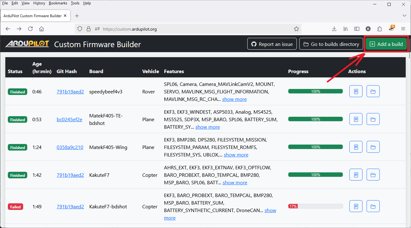
单击"加一个建筑" button located at the top right corner of the homepage.
Choose the vehicle, version, and board,in that order, for which you want to build the firmware.
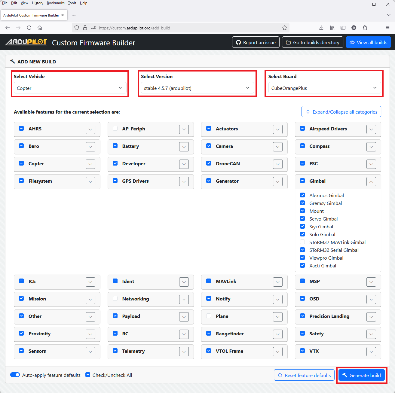
Select the features you wish to include in the firmware
- The default features for the board/vehicle will automatically be selected
- Some features depend on other features so when a feature is selected, all its dependencies will be automatically selected but if the feature is later deselected, the dependencies are not automatically deselected
- It is possible to select a set of features that will not fit on a board which will cause the build will fail.
Click the 'Generate' button. You will be redirected to the homepage, and a build log for the request you just submitted will appear.
Once the build is complete the build artifact will be downloaded automatically, You can also download it manually by clicking the 'Download' button next to your build request in the build list table. The button will be enabled only after a successful build.
Extract the downloaded build artifact. The extracted files will include the .apj firmware file along with other files
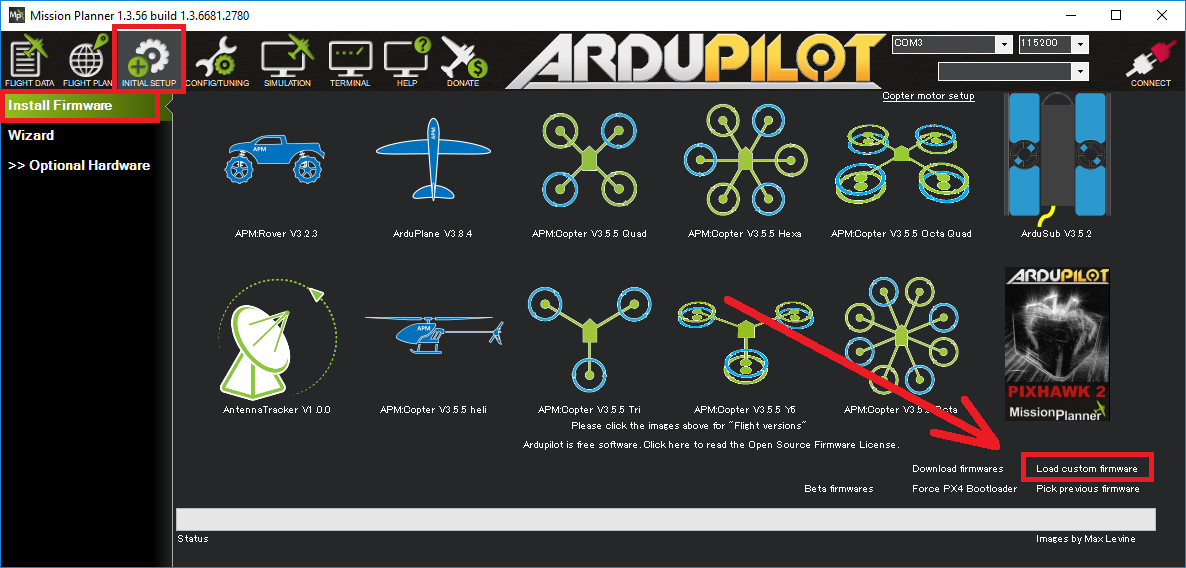
Use your GCS to install the .apj file onto your autopilot. If using Mission Planner, open the Install Firmware and click then "Load custom firmware" link


Versions
Latest
This is the current development branch of ArduPilot. It includes new features, enhancements, clean-ups, etc. but has not been through a release cycle of beta testing. It has been alpha tested and thoroughly tested in ArduPilot's Continuous Integration auto-test suite. Many experienced users select this to get the latest features but it has the highest risk, in terms of potential bugs.
Beta
This is a release of the development branch used for widespread testing and feedback. While the risk of major issues is low, it is expected that minor behavioral deviations may pop up. These are normally addressed in later beta releases of a major new release before declaring the code as a stable release.
Stable
These are fully released versions of the code. There are usually several minor releases for each major release number which correct any anomalies found during the beta testing phases. These releases, have the lowest risk. It is recommended that the highest numbered major/minor release be used in a given release sequence, unless an older version is needed.
说明:
The ArduPilot project is very careful about what is merged into our "point releases". Anything that goes into one has either been evaluated as being strictly limited in what impact it can have on existing systems, or as being an important bugfix. We encourage users to upgrade to any point release which is released, as they sometimes contain very important bugfixes.
Guide to Size Impacts
Often, the custom build server is used to create firmware with features that have been removed in the standard firmware to conserve flash space, but desired by the user. If a build fails to complete due to lack of flash, the user may remove features/sensors that are not needed in order to make room for those additional items wanted. In order to facilitate those choices, the table below shows what impact a feature's removal has on flash size. Note that a removed feature in this list automatically removed all features dependent upon it.
说明:
the exact numbers of bytes will change slightly over time due to code changes, but this table should be accurate enough to make decisions on removal candidates to gain flash space.
| FEATURE | PLANE | COPTER | ROVER |
|---|---|---|---|
| AP_SCRIPTING_ENABLED | 175800 | 182160 | 171688 |
| HAL_NAVEKF3_AVAILABLE | 171392 | 171400 | 170784 |
| HAL_QUADPLANE_ENABLED | 139776 | na | na |
| HAL_ENABLE_DRONECAN_DRIVERS | 97480 | 96120 | 95936 |
| HAL_LOGGING_ENABLED | 88792 | 95704 | 86400 |
| HAL_MOUNT_ENABLED | 67268 | 67300 | 67116 |
| AP_RANGEFINDER_ENABLED | 46568 | 48056 | 46272 |
| HAL_GYROFFT_ENABLED | 42396 | 42308 | 41772 |
| OSD_ENABLED | 40992 | 40568 | 40472 |
| AP_RCPROTOCOL_ENABLED | 35888 | 35888 | 35904 |
| AP_FILESYSTEM_ROMFS_ENABLED | 32920 | 32912 | 32912 |
| HAL_MSP_ENABLED | 31848 | 31808 | 31816 |
| AP_BOOTLOADER_FLASHING_ENABLED | 31648 | 31648 | 31640 |
| AP_OPTICALFLOW_ENABLED | 29232 | 33816 | 29216 |
| HAL_EXTERNAL_AHRS_ENABLED | 29120 | 29112 | 29008 |
| HAL_ADSB_ENABLED | 25760 | 25800 | 19112 |
| AP_AIRSPEED_ENABLED | 25440 | 22984 | 23468 |
| AP_CAMERA_ENABLED | 25192 | 25192 | 25192 |
| AP_FRSKY_TELEM_ENABLED | 24504 | 24288 | 24376 |
| AP_FRSKY_SPORT_TELEM_ENABLED | 22088 | 21952 | 22040 |
| AP_FRSKY_SPORT_PASSTHROUGH_ENABLED | 18376 | 18240 | 18328 |
| HAL_WITH_MSP_DISPLAYPORT | 18328 | 18248 | 18240 |
| AP_FENCE_ENABLED | 17488 | 50360 | 44748 |
| HAL_SOLO_GIMBAL_ENABLED | 17432 | 17192 | 17424 |
| HAL_EFI_ENABLED | 14724 | 14816 | 14784 |
| COMPASS_CAL_ENABLED | 14624 | 14592 | 14600 |
| EK3_FEATURE_OPTFLOW_FUSION | 12824 | 12816 | 12832 |
| AP_GPS_UBLOX_ENABLED | 12504 | 12368 | 12440 |
| AP_RCPROTOCOL_CRSF_ENABLED | 11648 | 11640 | 11648 |
| AP_BARO_PROBE_EXTERNAL_I2C_BUSES | 11296 | 11296 | 11296 |
| OSD_PARAM_ENABLED | 11116 | 11596 | 8152 |
| HAL_VISUALODOM_ENABLED | 10616 | 10520 | 10648 |
| AP_EXTERNAL_AHRS_INERTIALLABS_ENABLED | 10328 | 10344 | 10224 |
| HAL_CRSF_TELEM_ENABLED | 9680 | 9680 | 9680 |
| AP_RPM_ENABLED | 9616 | 5504 | 5648 |
| HAL_MOUNT_XACTI_ENABLED | 8984 | 8968 | 8976 |
| AP_VIDEOTX_ENABLED | 8956 | 9036 | 9060 |
| HAL_PICCOLO_CAN_ENABLE | 8920 | 8920 | 8920 |
| AP_BEACON_ENABLED | 8840 | 14424 | 14440 |
| AP_RCPROTOCOL_SRXL2_ENABLED | 8592 | 8584 | 8584 |
| HAL_GENERATOR_ENABLED | 8424 | 8544 | 8416 |
| HAL_ADSB_SAGETECH_MXS_ENABLED | 8376 | 8376 | 8592 |
| HAL_INS_TEMPERATURE_CAL_ENABLE | 7952 | 8040 | 8000 |
| AC_PRECLAND_ENABLED | 7832 | 10144 | 8968 |
| HAL_SOARING_ENABLED | 7656 | na | na |
| HAL_PROXIMITY_ENABLED | 7272 | 26824 | 25472 |
| HAL_MOUNT_TOPOTEK_ENABLED | 7092 | 7092 | 7092 |
| AP_INERTIALSENSOR_HARMONICNOTCH_ENABLED | 6368 | 9824 | 5128 |
| AP_GPS_NMEA_ENABLED | 6176 | 6176 | 6184 |
| HAL_MOUNT_SIYI_ENABLED | 6000 | 5992 | 5992 |
| HAL_LANDING_DEEPSTALL_ENABLED | 5712 | 120 | 120 |
| AP_CAMERA_RUNCAM_ENABLED | 5616 | 5600 | 5592 |
| AP_OPTICALFLOW_PIXART_ENABLED | 5536 | 5536 | 5536 |
| AP_SERVO_TELEM_ENABLED | 5520 | 4864 | 5344 |
| GPS_MOVING_BASELINE | 5096 | 5040 | 5088 |
| AP_NOTIFY_TONEALARM_ENABLED | 4992 | 4984 | 4984 |
| EK3_FEATURE_DRAG_FUSION | 4984 | 4984 | 4984 |
| AP_GPS_SBF_ENABLED | 4904 | 4904 | 4904 |
| AP_EXTERNAL_AHRS_VECTORNAV_ENABLED | 4824 | 4816 | 4832 |
| HAL_MOUNT_VIEWPRO_ENABLED | 4812 | 4812 | 4804 |
| AP_GPS_SBP_ENABLED | 4792 | 4864 | 4880 |
| AP_MAVLINK_FTP_ENABLED | 4656 | 4648 | 4648 |
| AP_CRASHDUMP_ENABLED | 4652 | 4636 | 4644 |
| AP_ICENGINE_ENABLED | 4600 | 144 | 144 |
| HAL_SPEKTRUM_TELEM_ENABLED | 4576 | 4576 | 4576 |
| AP_RELAY_ENABLED | 4464 | 4376 | 4528 |
| AP_SERIALMANAGER_REGISTER_ENABLED | 4376 | 4448 | 4456 |
| AP_PROXIMITY_DRONECAN_ENABLED | 4248 | 2024 | 2024 |
| HAL_DISPLAY_ENABLED | 4176 | 4168 | 4168 |
| AP_BATTERY_SMBUS_ENABLED | 4172 | 4172 | 4172 |
| AP_RANGEFINDER_VL53L1X_ENABLED | 4160 | 4152 | 4152 |
| AP_QUICKTUNE_ENABLED | 4136 | na | na |
| AP_TUNING_ENABLED | 4072 | na | na |
| AP_ADVANCEDFAILSAFE_ENABLED | 4032 | 472 | 472 |
| AP_CAN_SLCAN_ENABLED | 4016 | 4096 | 4032 |
| AP_RCPROTOCOL_GHST_ENABLED | 3680 | 3672 | 3672 |
| HAL_WITH_FRSKY_TELEM_BIDIRECTIONAL | 3632 | 3496 | 3592 |
| AP_CAMERA_INFO_FROM_SCRIPT_ENABLED | 3480 | 3480 | 3480 |
| HAL_ADSB_UCP_ENABLED | 3424 | 3416 | 3416 |
| AP_FETTEC_ONEWIRE_ENABLED | 3312 | 3296 | 3248 |
| EK3_FEATURE_EXTERNAL_NAV | 3272 | 3272 | 3272 |
| AP_FILESYSTEM_PARAM_ENABLED | 3208 | 3208 | 3208 |
| AP_RANGEFINDER_VL53L0X_ENABLED | 3200 | 3200 | 3200 |
| AP_SMARTAUDIO_ENABLED | 3160 | 3144 | 3144 |
| AP_GPS_BLENDED_ENABLED | 3096 | 3096 | 3096 |
| HAL_MSP_OPTICALFLOW_ENABLED | 2944 | 2952 | 2952 |
| AP_COMPASS_DRONECAN_ENABLED | 2872 | 2872 | 2872 |
| HAL_MSP_RANGEFINDER_ENABLED | 2856 | 2864 | 2864 |
| AP_DRONECAN_SERIAL_ENABLED | 2800 | 2800 | 2800 |
| AP_DRONECAN_HOBBYWING_ESC_SUPPORT | 2792 | 2792 | 2792 |
| HAL_RALLY_ENABLED | 2768 | 2848 | 3016 |
| AP_COMPASS_BMM350_ENABLED | 2656 | 2656 | 2656 |
| AP_FOLLOW_ENABLED | 2608 | 4448 | 3928 |
| AP_FILESYSTEM_SYS_ENABLED | 2576 | 2576 | 2568 |
| MODE_AUTOLAND_ENABLED | 2488 | na | na |
| HAL_ADSB_SAGETECH_ENABLED | 2472 | 2464 | 2464 |
| AP_AIRSPEED_DRONECAN_ENABLED | 2456 | 2456 | 2456 |
| AP_COMPASS_HMC5843_ENABLED | 2456 | 2448 | 2448 |
| AP_GENERATOR_IE_2400_ENABLED | 2392 | 2392 | 2392 |
| AP_DRONECAN_SEND_GPS | 2360 | 2352 | 2352 |
| AP_EXTERNAL_AHRS_MICROSTRAIN7_ENABLED | 2336 | 2336 | 2336 |
| AP_GPS_SBP2_ENABLED | 2320 | 2376 | 2440 |
| AP_RANGEFINDER_LWI2C_ENABLED | 2320 | 2320 | 2320 |
| AP_GHST_TELEM_ENABLED | 2304 | 2304 | 2304 |
| AP_BATTERY_INA2XX_ENABLED | 2288 | 2280 | 2280 |
| HAL_MSP_SENSORS_ENABLED | 2288 | 2288 | 2288 |
| AP_AIRSPEED_MSP_ENABLED | 2272 | 2272 | 2272 |
| AP_BARO_MSP_ENABLED | 2272 | 2280 | 2280 |
| AP_COMPASS_MSP_ENABLED | 2272 | 2280 | 2280 |
| HAL_MSP_GPS_ENABLED | 2272 | 2280 | 2280 |
| AP_PLANE_OFFBOARD_GUIDED_SLEW_ENABLED | 2264 | na | na |
| AP_AIRSPEED_SDP3X_ENABLED | 2256 | 2248 | 2256 |
| AP_FILESYSTEM_MISSION_ENABLED | 2200 | 2200 | 2200 |
| AP_GPS_GSOF_ENABLED | 2192 | 2184 | 2184 |
| AP_FILTER_ENABLED | 2168 | 2128 | 2136 |
| AP_GENERATOR_RICHENPOWER_ENABLED | 2168 | 2248 | 2168 |
| AP_GENERATOR_LOWEHEISER_ENABLED | 4108 | 4104 | 4124 |
| HAL_HIGH_LATENCY2_ENABLED | 2168 | 2024 | 1920 |
| AP_COMPASS_LIS3MDL_ENABLED | 2128 | 2128 | 2128 |
| AP_COMPASS_MMC3416_ENABLED | 2120 | 2112 | 2112 |
| AP_BARO_DRONECAN_ENABLED | 2080 | 2080 | 2080 |
| AP_INERTIALSENSOR_BATCHSAMPLER_ENABLED | 2064 | 2072 | 2056 |
| AP_GPS_NMEA_UNICORE_ENABLED | 2008 | 2000 | 2000 |
| AP_COMPASS_CALIBRATION_FIXED_YAW_ENABLED | 1976 | 1976 | 1976 |
| HAL_BUTTON_ENABLED | 1960 | 1984 | 2072 |
| AP_EFI_SERIAL_MS_ENABLED | 1944 | 1936 | 1936 |
| AP_ROBOTISSERVO_ENABLED | 1936 | 1872 | 1960 |
| HAL_PARACHUTE_ENABLED | 1912 | 1824 | 616 |
| HAL_MOUNT_SERVO_ENABLED | 1880 | 1688 | 1688 |
| AP_LANDINGGEAR_ENABLED | 1824 | 1360 | na |
| AP_EFI_DRONECAN_ENABLED | 1752 | 1752 | 1752 |
| AP_VOLZ_ENABLED | 1752 | 2048 | 1840 |
| AP_EXTERNAL_AHRS_MICROSTRAIN5_ENABLED | 1744 | 1736 | 1736 |
| AP_SERVORELAYEVENTS_ENABLED | 1696 | 1712 | 1712 |
| AP_EFI_CURRAWONG_ECU_ENABLED | 1680 | 1672 | 1672 |
| AP_RSSI_ENABLED | 1672 | 1728 | 1808 |
| AP_COMPASS_IST8310_ENABLED | 1656 | 1656 | 1656 |
| AP_EFI_SERIAL_HIRTH_ENABLED | 1656 | 1688 | 1648 |
| AP_AIRSPEED_MS4525_ENABLED | 1648 | 1640 | 1640 |
| AP_BARO_BMP085_ENABLED | 1648 | 1648 | 1648 |
| AP_RANGEFINDER_WASP_ENABLED | 1648 | 1640 | 1640 |
| AP_GRIPPER_ENABLED | 1644 | 2068 | 1756 |
| HAL_NMEA_OUTPUT_ENABLED | 1632 | 1688 | 1688 |
| AP_SDCARD_STORAGE_ENABLED | 1624 | 1480 | 1488 |
| AP_GPS_ERB_ENABLED | 1616 | 1480 | 1552 |
| AP_AIRSPEED_MS5525_ENABLED | 1600 | 1600 | 1584 |
| AP_BARO_DPS280_ENABLED | 1600 | 1592 | 1592 |
| AP_BARO_SPL06_ENABLED | 1600 | 1592 | 1592 |
| AP_COMPASS_BMM150_ENABLED | 1600 | 1592 | 1592 |
| AP_TRAMP_ENABLED | 1584 | 1600 | 1568 |
| AP_COMPASS_RM3100_ENABLED | 1568 | 1560 | 1560 |
| AP_TEMPERATURE_SENSOR_ENABLED | 1560 | 1560 | 1552 |
| HAL_MOUNT_GREMSY_ENABLED | 1560 | 1560 | 1560 |
| AP_AIRSPEED_AUAV_ENABLED | 1544 | 1544 | 1528 |
| AP_MOTORS_FRAME_QUAD_ENABLED | 1544 | 1376 | na |
| AP_CAMERA_MAVLINKCAMV2_ENABLED | 1512 | 1512 | 1512 |
| AP_GPS_NOVA_ENABLED | 1512 | 1512 | 1512 |
| AP_RANGEFINDER_BENEWAKE_TFMINIPLUS_ENABLED | 1472 | 1472 | 1472 |
| HAL_MOUNT_ALEXMOS_ENABLED | 1472 | 1464 | 1464 |
| AP_RC_CHANNEL_AUX_FUNCTION_STRINGS_ENABLED | 1464 | 1456 | 1456 |
| AP_COMPASS_IST8308_ENABLED | 1424 | 1416 | 1416 |
| AP_BARO_FBM320_ENABLED | 1392 | 1392 | 1392 |
| AP_KDECAN_ENABLED | 1392 | 1248 | 1264 |
| AP_SCRIPTING_SERIALDEVICE_ENABLED | 1376 | 1352 | 1336 |
| AP_RANGEFINDER_DRONECAN_ENABLED | 1360 | 1360 | 1360 |
| AP_DRONECAN_HIMARK_SERVO_SUPPORT | 1352 | 1344 | 1344 |
| AP_BARO_BMP388_ENABLED | 1320 | 1320 | 1320 |
| AP_BARO_BMP280_ENABLED | 1312 | 1304 | 1304 |
| AP_COMPASS_QMC5883L_ENABLED | 1312 | 1304 | 1304 |
| AP_MOTORS_FRAME_OCTA_ENABLED | 1312 | 1312 | na |
| AP_RPM_PIN_ENABLED | 1248 | 1552 | 1552 |
| AP_CUSTOMROTATIONS_ENABLED | 1216 | 1232 | 1216 |
| AP_OPTICALFLOW_HEREFLOW_ENABLED | 1168 | 1160 | 1160 |
| HAL_MOUNT_STORM32SERIAL_ENABLED | 1156 | 1148 | 1148 |
| AP_FRSKY_D_TELEM_ENABLED | 1144 | 1136 | 1136 |
| HAL_CRSF_TELEM_TEXT_SELECTION_ENABLED | 1120 | 1120 | 1120 |
| AC_PRECLAND_IRLOCK_ENABLED | 1112 | 1112 | 1112 |
| AP_GPS_SIRF_ENABLED | 1104 | 968 | 1048 |
| AP_BARO_LPS2XH_ENABLED | 1040 | 1040 | 1040 |
| AP_RANGEFINDER_PULSEDLIGHTLRF_ENABLED | 1024 | 1024 | 1024 |
| AP_RANGEFINDER_JRE_SERIAL_ENABLED | 1016 | 1008 | 1008 |
| HAL_ADSB_UAVIONIX_MAVLINK_ENABLED | 992 | 984 | 984 |
| AP_RPM_DRONECAN_ENABLED | 984 | 984 | 984 |
| AP_AIRSPEED_DLVR_ENABLED | 976 | 976 | 976 |
| AP_RANGEFINDER_TRI2C_ENABLED | 968 | 968 | 968 |
| HAL_PLUSCODE_ENABLE | 960 | 944 | 944 |
| AP_EXTENDED_ESC_TELEM_ENABLED | 944 | 936 | 928 |
| AP_RANGEFINDER_BLPING_ENABLED | 936 | 936 | 936 |
| AP_RANGEFINDER_NMEA_ENABLED | 936 | 928 | 880 |
| AP_MOTORS_FRAME_OCTAQUAD_ENABLED | 896 | 896 | na |
| AP_CAMERA_SOLOGIMBAL_ENABLED | 888 | 888 | 888 |
| AP_RCPROTOCOL_SRXL_ENABLED | 888 | 888 | 888 |
| AP_CAMERA_MOUNT_ENABLED | 880 | 872 | 872 |
| HAL_MOUNT_CADDX_ENABLED | 880 | 872 | 872 |
| AP_AIRSPEED_ASP5033_ENABLED | 856 | 856 | 856 |
| HAL_OSD_SIDEBAR_ENABLE | 848 | 848 | 848 |
| AP_RANGEFINDER_LIGHTWARE_SERIAL_ENABLED | 832 | 832 | 832 |
| AP_EFI_NWPWU_ENABLED | 824 | 816 | 816 |
| AP_NOTIFY_MAVLINK_LED_CONTROL_SUPPORT_ENABLED | 824 | 824 | 824 |
| AP_RANGEFINDER_TOFSENSEF_I2C_ENABLED | 824 | 824 | 824 |
| HAL_MOUNT_STORM32MAVLINK_ENABLED | 824 | 824 | 824 |
| AP_MAVLINK_MSG_DEVICE_OP_ENABLED | 816 | 816 | 816 |
| AP_OPTICALFLOW_PX4FLOW_ENABLED | 816 | 808 | 808 |
| AP_RANGEFINDER_PWM_ENABLED | 808 | 800 | 800 |
| AP_BARO_EXTERNALAHRS_ENABLED | 792 | 792 | 800 |
| AP_RANGEFINDER_LEDDARVU8_ENABLED | 776 | 776 | 776 |
| AP_NOTIFY_NCP5623_ENABLED | 768 | 760 | 760 |
| AP_OPTICALFLOW_CXOF_ENABLED | 768 | 760 | 760 |
| AP_RANGEFINDER_RDS02UF_ENABLED | 768 | 760 | 760 |
| AP_MAVLINK_MSG_SERIAL_CONTROL_ENABLED | 760 | 760 | 760 |
| AP_CAMERA_SEND_FOV_STATUS_ENABLED | 752 | 752 | 752 |
| AP_BARO_BMP581_ENABLED | 736 | 736 | 736 |
| AP_MAVLINK_MSG_FLIGHT_INFORMATION_ENABLED | 728 | 720 | 752 |
| AP_OPTICALFLOW_UPFLOW_ENABLED | 728 | 728 | 728 |
| HAL_BARO_WIND_COMP_ENABLED | 712 | 680 | 728 |
| AP_EFI_SERIAL_LUTAN_ENABLED | 704 | 704 | 704 |
| AP_GPS_MAV_ENABLED | 704 | 704 | 704 |
| AP_MOTORS_FRAME_Y6_ENABLED | 704 | 704 | na |
| AP_RCPROTOCOL_ST24_ENABLED | 704 | 704 | 704 |
| AP_BATTERY_FUELFLOW_ENABLED | 696 | 696 | 696 |
| AP_RANGEFINDER_MAXSONARI2CXL_ENABLED | 688 | 680 | 680 |
| AP_BATTERY_FUELLEVEL_ANALOG_ENABLED | 680 | 672 | 672 |
| AP_BATTERY_SUM_ENABLED | 680 | 672 | 672 |
| AP_MOTORS_FRAME_HEXA_ENABLED | 672 | 672 | na |
| AP_RANGEFINDER_LEDDARONE_ENABLED | 672 | 672 | 672 |
| AP_RANGEFINDER_USD1_SERIAL_ENABLED | 640 | 640 | 640 |
| AP_RCPROTOCOL_SUMD_ENABLED | 616 | 608 | 608 |
| HAL_TORQEEDO_ENABLED | 608 | 608 | 7992 |
| AP_CAMERA_SERVO_ENABLED | 600 | 600 | 600 |
| AP_RCPROTOCOL_SBUS_ENABLED | 592 | 584 | 592 |
| AP_COMPASS_EXTERNALAHRS_ENABLED | 584 | 584 | 600 |
| AP_SBUSOUTPUT_ENABLED | 560 | 472 | 544 |
| AP_OPTICALFLOW_MAV_ENABLED | 552 | 544 | 544 |
| AP_CAN_LOGGING_ENABLED | 544 | 416 | 488 |
| COMPASS_LEARN_ENABLED | 512 | 504 | 504 |
| AP_RANGEFINDER_HC_SR04_ENABLED | 504 | 504 | 504 |
| AP_BATTERY_WATT_MAX_ENABLED | 496 | na | na |
| AP_OAPATHPLANNER_ENABLED | 488 | 19016 | 16768 |
| AP_RANGEFINDER_ANALOG_ENABLED | 488 | 480 | 480 |
| AP_RANGEFINDER_MAVLINK_ENABLED | 488 | 488 | 488 |
| AP_GENERATOR_IE_650_800_ENABLED | 472 | 464 | 464 |
| AP_MAVLINK_MSG_MISSION_REQUEST_ENABLED | 456 | 448 | 448 |
| AP_RANGEFINDER_TERARANGER_SERIAL_ENABLED | 448 | 448 | 448 |
| AP_RANGEFINDER_NOOPLOOP_ENABLED | 440 | 432 | 432 |
| AP_RCPROTOCOL_IBUS_ENABLED | 440 | 432 | 432 |
| AP_AVOIDANCE_ENABLED | 432 | 15680 | 13232 |
| AP_BATTERY_FUELLEVEL_PWM_ENABLED | 392 | 392 | 392 |
| AP_BATTERY_SYNTHETIC_CURRENT_ENABLED | 392 | 392 | 392 |
| AP_RANGEFINDER_LANBAO_ENABLED | 392 | 384 | 384 |
| AP_RANGEFINDER_GYUS42V2_ENABLED | 384 | 384 | 384 |
| AP_MAVLINK_MSG_RELAY_STATUS_ENABLED | 376 | 376 | 376 |
| AP_RCPROTOCOL_MAVLINK_RADIO_ENABLED | 376 | 368 | 368 |
| AP_MAVLINK_MAV_CMD_SET_HAGL_ENABLED | 360 | na | na |
| AP_CAMERA_MAVLINK_ENABLED | 352 | 344 | 344 |
| AP_RANGEFINDER_LUA_ENABLED | 352 | 352 | 352 |
| AP_RANGEFINDER_MAXBOTIX_SERIAL_ENABLED | 352 | 344 | 344 |
| AP_MOTORS_FRAME_DODECAHEXA_ENABLED | 344 | 344 | na |
| AC_PRECLAND_COMPANION_ENABLED | 320 | 312 | 312 |
| AP_EFI_MAV_ENABLED | 312 | 312 | 312 |
| AP_CAMERA_RELAY_ENABLED | 304 | 296 | 296 |
| AP_MOTORS_FRAME_DECA_ENABLED | 296 | 296 | na |
| HAL_SPRAYER_ENABLED | 280 | 1224 | 1016 |
| AP_FILESYSTEM_FORMAT_ENABLED | 272 | 272 | 272 |
| AP_RANGEFINDER_BENEWAKE_CAN_ENABLED | 272 | 264 | 264 |
| AP_NOTIFY_NEOPIXEL_ENABLED | 264 | 264 | 264 |
| AP_INERTIALSENSOR_KILL_IMU_ENABLED | 256 | 240 | 240 |
| AP_MAVLINK_SERVO_RELAY_ENABLED | 256 | 248 | 248 |
| AP_RANGEFINDER_TOFSENSEP_CAN_ENABLED | 256 | 256 | 256 |
| AP_AIRSPEED_ANALOG_ENABLED | 248 | 248 | 248 |
| AP_NOTIFY_PROFILED_ENABLED | 224 | 216 | 216 |
| AP_MAVLINK_MSG_RC_CHANNELS_RAW_ENABLED | 216 | 208 | 208 |
| AP_RANGEFINDER_USD1_CAN_ENABLED | 216 | 208 | 208 |
| AP_RCPROTOCOL_PPMSUM_ENABLED | 216 | 208 | 208 |
| AP_CAMERA_SEND_THERMAL_RANGE_ENABLED | 176 | 176 | 176 |
| AP_RPM_HARMONICNOTCH_ENABLED | 176 | 176 | 176 |
| AP_RANGEFINDER_BENEWAKE_TF02_ENABLED | 144 | 144 | 144 |
| AP_MAVLINK_MSG_VIDEO_STREAM_INFORMATION_ENABLED | 136 | 136 | 136 |
| AP_RANGEFINDER_BENEWAKE_TF03_ENABLED | 136 | 136 | 136 |
| AP_RANGEFINDER_BENEWAKE_TFMINI_ENABLED | 136 | 136 | 136 |
| AP_RPM_GENERATOR_ENABLED | 136 | 128 | 128 |
| AP_RPM_EFI_ENABLED | 128 | 128 | 128 |
| AP_RPM_ESC_TELEM_ENABLED | 128 | 120 | 120 |
| AP_NOTIFY_MAVLINK_PLAY_TUNE_SUPPORT_ENABLED | 96 | 88 | 88 |
| AP_PROXIMITY_RANGEFINDER_ENABLED | 80 | 792 | 792 |
| AP_WINCH_ENABLED | 64 | 5060 | 64 |
| AP_MISSION_NAV_PAYLOAD_PLACE_ENABLED | 40 | 2096 | 32 |
| AP_AIS_ENABLED | 24 | 1048 | 7404 |
| AP_PROXIMITY_CYGBOT_ENABLED | na | 936 | 936 |
| AP_PROXIMITY_MR72_ENABLED | na | na | na |
| AP_SERIALMANAGER_IMUOUT_ENABLED | na | na | na |
| AP_TEMPCALIBRATION_ENABLED | na | 1328 | na |
| AP_WINCH_DAIWA_ENABLED | na | 2452 | na |
| AP_WINCH_PWM_ENABLED | na | 560 | na |
| HAL_HOTT_TELEM_ENABLED | na | na | na |
| HAL_MOUNT_XFROBOT_ENABLED | na | na | na |
| MODE_BRAKE_ENABLED | na | 688 | na |
| MODE_FLIP_ENABLED | na | 1296 | na |
| MODE_FLOWHOLD_ENABLED | na | 4616 | na |
| MODE_FOLLOW_ENABLED | na | 2296 | 1488 |
| MODE_GUIDED_NOGPS_ENABLED | na | 240 | na |
| MODE_SPORT_ENABLED | na | na | na |
| MODE_SYSTEMID_ENABLED | na | 4208 | na |
| MODE_TURTLE_ENABLED | na | 1896 | na |
| MODE_ZIGZAG_ENABLED | na | 4784 | na |
| AP_COPTER_AHRS_AUTO_TRIM_ENABLED | na | 472 | na |
| AP_DRONECAN_VOLZ_FEEDBACK_ENABLED | na | na | na |
| AP_INERTIALSENSOR_FAST_SAMPLE_WINDOW_ENABLED | na | 2968 | na |
| AP_PROXIMITY_LIGHTWARE_SF40C_ENABLED | na | 1816 | 1816 |
| AP_PROXIMITY_LIGHTWARE_SF45B_ENABLED | na | 1760 | 1760 |
| AP_PROXIMITY_RPLIDARA2_ENABLED | na | 1504 | 1504 |
| AP_PROXIMITY_TERARANGERTOWEREVO_ENABLED | na | 992 | 992 |
| AP_PROXIMITY_TERARANGERTOWER_ENABLED | na | 656 | 656 |
| AP_PROXIMITY_MAV_ENABLED | na | 1800 | 1800 |
| AP_AIRSPEED_NMEA_ENABLED | na | na | 888 |
Build Server Versions
Before deploying new features to the main instance of the application, we test them on a dedicated testing instance. This testing environment is accessible at custom-beta.ardupilot.org. Feel free to use the beta features and provide your valuable feedback to help us improve the application.
[copywiki destination="copter,plane,rover,planner,blimp,sub"]
【本页后半部分仍为英文原文摘录,补译中。】
译自 ArduPilot Copter「ArduPilot Custom Firmware Builder」· 查看原文 · CC BY-SA 3.0
安装 SD 卡
[copywiki 目的地='copter,plane,rover,planner,blimp,sub,dev'].
通过SD卡加裝固 没問題 看来
可以通过将一个专门命名的文件放在SD卡上并运行自动驾驶员的起动器(例如通过电循环板)来更新某些自动驾驶上的ArduPilot固件.
说明:
目前只有少数自动驾驶员有这种能力. 参见以下指示,以确定自动驾驶员是否具有此特性. 只有使用MMC连接的SD卡的基于H7的自动驾驶器 36 才能做到这一点,而并非所有确实添加过Revolution 的功能,至今为止.
我为什么要这么做?
这种技术可能有几个用途:
- 机体的USB港口没有方便可靠的通道
- 希望通过遥测无线电更新机体固件
- 机体位置偏僻,当地运营商可能与普通接口难以更新固件. 这使得OEMs能够远程在用户的SD卡上添加更新的文件,这些卡会上传到机体的下一靴子上.
我的自动驾驶能胜任吗?
为此,必须具备若干要素:
- 自动驾驶员必须有SD卡能力
- The SD card must be enabled in its bootloader
- The bootloader code and flashing firmware must be enabled in the autopilots firmware definition files (hwdefs)
To see if a given autopilot has this capability, you can check in its firmware folder on the Firmware build server to see if it has a xxxxxx.abin file present.
The Bootloader
A bootloader capable of flashing from the SD card is required (and the autopilot must have SD card capability, obviously). Newer autopilot's with SD cards may or may not have this capability and a capable bootloader included in their hardware definition (if not, see **Building capable firmware yourself **).
If the autopilot firmware currently provides this capability, updating your current bootloader may be required to support flashing from SD card. Note that updating the autopilot's bootloader is an operation which can make your board non-operational, and difficult to recover. More-so with boards that do not expose a "boot0" pin, such as the CubeOrange. Be aware of this risk, and be prepared to spend considerable time recovering a board if something bad happens when updating the bootloader.
**The instructions on updating the bootloader ** can be followed to update your bootloader; be aware that you must use a recent firmware (4.5 or higher) to obtain a suitable bootloader.
The Firmware File
The file to be loaded onto the SD card is of a specially named "xxxxx.abin" file created for this purpose. This is a binary file with a small amount of text providing some information about the binary. Most notably, a checksum which the bootloader will verify before attempting to flash the board.
Boards which support flash-from-sdcard will also have .abin files available for download from the Firmware build server.
Firmware File Name
The filename which is used when generating firmware is *not* the correct name to use when placing the firmware on the SD card. When the .abin files are generated they contain the vehicle name, for example, "arduplane.abin".
There is only one correct filename that may be used to flash-from-sdcard; this is ardupilot.abin. When placing the file on the SD card, ensure the file has been renamed to ardupilot.abin.
Transferring the File to the SD card
This can be done in your operating system as you would ordinarily interact with the SD card (e.g. file browser).
You can also transfer the file to the SD card's base directory via MAVFTP using Mission Planner or similar GCS

Ensure the file is the correct size before continuing.
After the transfer is complete, the directory listing should look something like this:
RTL> ftp put /home/pbarker/arducopter.abin ardupilot.abin
RTL> Putting /home/pbarker/arducopter.abin as ardupilot.abin
Sent file of length  1847687
RTL> ftp list
RTL> Listing /
 D APM
   ardupilot.abin   1847687
Total size 1804.38 kByte
Triggering the Flash Update
Power cycle the board to enter the bootloader which will automatically check for the firmware update file and begin flashing it. Alternatively to avoid the powercycle the autopilot may be rebooted via a PREFLIGHT_REBOOT_SHUTDOWN command with the 'Param1' field set to 3 (ie. "Reboot autopilot and keep it in the bootloader until upgraded")
It should take roughly 1 minute to verify the firmware and flash it to the vehicle's internal flash.
If the process completes successfully the file will renamed to ardupilot-flashed.abin. The vehicle should proceed to boot the firmware once flashing is complete.
Troubleshooting
Several things can go wrong with the firmware flash, but some diagnostics are available to help work out what the problem might be.
- At each stage of the flashing process, the
ardupilot.abinfile is renamed to reflect the stage- if the file is called
ardupilot-verify.abinthen the process failed when trying to checksum the file, or the board was interrupted when doing so.- if the file is called
ardupilot-verify-failed.abinthen the checksum the bootloader calculated did not match the bootloader in the.abinmetadata.- if the file is called
ardupilot-flash.abinthe process failed when writing the firmware, or the board was interrupted while doing so. The board is unlikely to boot into an ArduPilot firmware if this has happened, so a re-flash will be required.- if the file is called
ardupilot-flashed.abinyou should not need this "troubleshooting" section, as the flash process has succeeded!
Building the firmware yourself
If the autopilot has an SD card capability but no SD Card flash-able firmware is present on the Firmware build server, you can build the firmware yourself. You must setup a build environment and then modify the autopilot's hwdefs to build a capable bootloader and an xxxx.abin firmware, see building-the-code.
In the hwdef-bl.dat file you must include this:
define AP_BOOTLOADER_FLASH_FROM_SD_ENABLED 1
define FATFS_HAL_DEVICE SDCD1
define HAL_OS_FATFS_IO 1
# FATFS support:
define CH_CFG_USE_MEMCORE 1
define CH_CFG_USE_HEAP 1
define CH_CFG_USE_SEMAPHORES 0
define CH_CFG_USE_MUTEXES 1
define CH_CFG_USE_DYNAMIC 1
define CH_CFG_USE_WAITEXIT 1
define CH_CFG_USE_REGISTRY 1
- Also you must include the SD card setup. See the MatekH743 autopilot definition for an example.
In the hwdef.dat file you must include this:
env BUILD_ABIN True
When you build the firmware you will see, note the .abin file is created:
     BUILD SUMMARY
Build directory: /home/pbarker/rc/ardupilot/build/CubeOrange
Target         Text (B)  Data (B)  BSS (B)  Total Flash Used (B)  Free Flash (B)  External Flash Used (B)
---------------------------------------------------------------------------------------------------------
bin/arduplane   1868612      3536   258740               1872148           93928  Not Applicable

Build commands will be stored in build/CubeOrange/compile_commands.json
'plane' finished successfully (24.283s)
pbarker@fx:~/rc/ardupilot(master)$ ls -l build/CubeOrange/bin
total 18792
-rwxrwxr-x 1 pbarker pbarker 3135448 Sep 29 19:15 arduplane
-rw-rw-r-- 1 pbarker pbarker 1872247 Sep 29 19:15 arduplane.abin
-rw-rw-r-- 1 pbarker pbarker 1684192 Sep 29 19:15 arduplane.apj
-rwxrwxr-x 1 pbarker pbarker 1872152 Sep 29 19:15 arduplane.bin
-rw-rw-r-- 1 pbarker pbarker 5148900 Sep 29 19:15 arduplane.hex
-rw-rw-r-- 1 pbarker pbarker 5509380 Sep 29 19:15 arduplane_with_bl.hex
Demo Video
width: 100%
【本页后半部分仍为英文原文摘录,补译中。】
译自 ArduPilot Copter「Loading Firmware via SD Card」· 查看原文 · CC BY-SA 3.0
安装 GPS / 罗盘模块
[copywiki目的地="飞机,copter,rover,blimp,sub"].
UBlox GPS + 编码模块
一个UBlox GPS + Compass模块是ArduPilot兼容自动驾驶系统最常用的GPS. 这些模块有许多版本可供各制造商使用,推荐的模型是** 。
ArduPilot在启动后不久就自动配置GPS,所以不需要任何GPS相关的校准. 但是,必须校准**附件。

连接自动驾驶器

示例: 连接到 Pixhawk
连接GPS的6-pin DF13连接器到Pixhawk的"GPS"端口和
指南针与I2C端口的4位连接器。 或者说
罗盘可以首先通过一个I2C 拆分器如果附加其他 I2C 设备。

关于如何设置和使用第2GPS的详情可在**GPS Blending page ** page上找到.
说明:
baud 率由 UBlox 驱动程序设置( 设置)SERIAL4 BAUD = 38 is ignored).
说明:
ArduPilot supports many attached compasses, but only up to 3 compasses can be used during operation. See common-compass-setup-advanced.
Mounting the GPS Module
This module permits the GPS to be mounted separately from the flight control module so that it can have the best clear (view) of the sky and allows the compass to be distanced from interfering magnetic fields.
提示:
The recommended orientation is to mount the module with the arrow facing toward the front of the vehicle and in the same direction as the arrow on the autopilot.
When mounting the GPS+Compass module:
- Place the module on the outside of your vehicle (in an elevated position if appropriate) with a clear view of the sky, as far as possible from the motors and ESCs, with the arrow facing forward.
- Distance the module from DC power wiring and the batteries by at least 10cm. Use of a GPS mast is highly recommended.
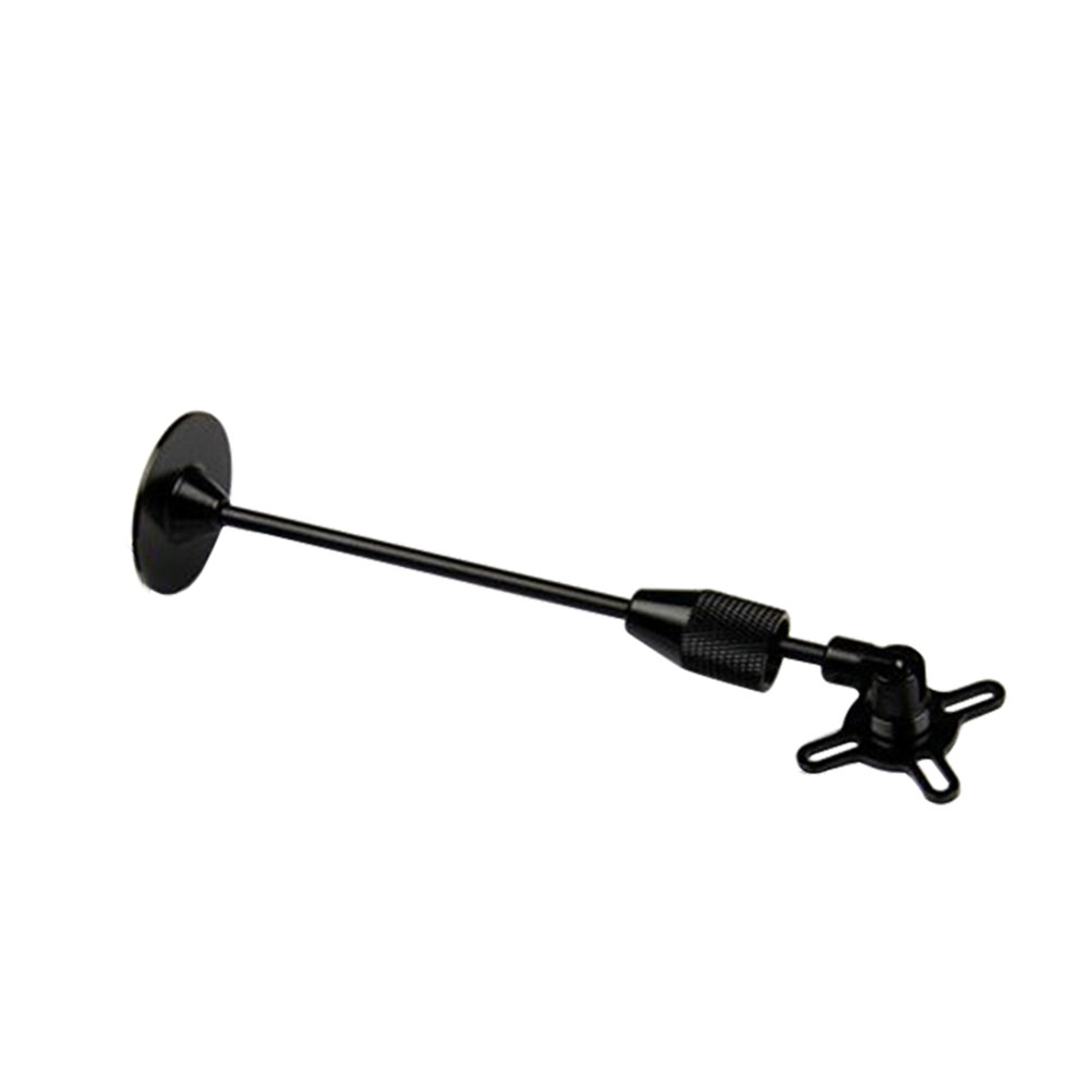
- Place the module clear of nearby iron containing metallic objects. (Use nylon or non magnetic stainless steel hardware and nylon or aluminum standoffs to mount the module).
- Twist power and ground wires where possible.

Setup in Mission Planner
**Compass Calibration in Mission Planner ** explains the simplest way to calibrate a compass mounted in the recommended orientation (arrows for autopilot and compass facing to front of vehicle).
**Advanced Compass Setup ** contains more detailed instructions for calibrating a compass if, for example, it has been mounted at some other orientation.
LED Indicators
The 3DR GPS+Compass module has two LED indicators: one for power (solid red) and one for GPS lock (flashing blue). Most GPS have an led indicator for 3D GPS lock acquisition.
| LEDs: | Behavior: |
| Power | Solid red when powered |
| GPS lock | Flashing blue when 3D GPS lock acquired |
Advanced Configuration
Advanced configuration of the UBlox GPS's internal settings is documented in **UBlox GPS Configuration **. But this is never used by the average user. ArduPilot automatically configures the gps during initialization.
【本页后半部分仍为英文原文摘录,补译中。】
译自 ArduPilot Copter「[copywiki destination="plane,copter,rover,blimp,sub"]」· 查看原文 · CC BY-SA 3.0
向 ChibiOS 板卡烧录固件
[copywiki 目的地='copter,plane,rover,planner,blimp,sub'].
在没有ArduPilot兼容器的情况下将固件装入板中
这些指令涵盖将ArduPilot装入尚未装有**ArduPilot兼容的bootloader **的自动驾驶器,这通常是一个配备Betaflight,INAV,或类似预先安装的固件的板. 在DFU(直接固件上传)模式下,ArduPilot新装机和固件一起装入USB。
这是一次性行动 一旦成功,董事会拥有一个ArduPilot bootload器,所有随后的更新都使用通常的地面站方法,如:其下, 其下, 并存于下, 其下, 并存于下, 并存于下, 并存于下, 并存于下..
(提供技术支助) 3 人 3 人 3 人 3 人 3 人 3 人 3 人 3 人 3 人 3 人 3 人 3 人 3 人 3 人 3 人 3 人 3 人 3 人 3 人 4 人 3 人 3 人 3 人 3 人 3 人 人 3 人 3 人3 人 支撑 3 人 人 3 人 3 人 3 人 3 人 人 3 人 3 人 人 人 3 人 3 3 人 3 人 人 人 3 人 3 人 3 人 3 人 人 3 人 人 人 人 3 人 人 人 ( 人 人 、 人 程序 、 ( 人 我不喜欢 ( 、 、 ( 你肯定 ( 、 、 、 、 、 、 、 程序 ( 小镇 、
在自动驾驶上安装ArduPilot涉及:
- 安装所需的驱动和闪存工具
- 正在下载
使用 bl.hex 的参数固件文件 - 把它装到DFU上
Download driver and flashing tool
The STM32CubeProgrammer will install the required DFU drivers and can be used to flash the firmware to autopilots in DFU mode. This is available for Windows, Linux, and MacOS systems. Download and install this program. You may be required to also install JAVA in order to setup this program.
Download the ArduPilot firmware
Follow **Download the Firmware ** to obtain the firmware for your board, selecting the arduXXX_with_bl.hex file. This file contains both the ArduPilot bootloader and the firmware, which is what DFU loading requires; the .apj files cannot be used here.
Upload the firmware to autopilot
Hold down the board's DFU button or temporarily bridge its "BOOT" pins, and plug in a USB cable (attached to your PC). Release button or unbridge once powered.
Open the windows device manager and look under "Universal Serial Bus devices" for "STM32 BOOTLOADER" to confirm that the board is in DFU mode.

Start the STM32CubeProgrammer


- Select the connection method: USB
- Make sure a USB port shows...that means the board is detected in DFU mode.
- Press "Connect"
- Then the boards cpu specifics will appear here.
- Press "Open file" to select the "arduXXX_with_bl.hex" file you downloaded.
- The file name will appear in the tab.

- Press "Download" to flash the file to the board.
You may now reboot the board and confirm the firmware is running **. Future firmware uploads can be done with the normal ground station method, see **common-loading-firmware-onto-pixhawk.
Loading firmware onto Boards with external flash
Some recent boards, most notably those from Seriously Pro Racing (http://www.seriouslypro.com/), use MCUs with small amounts of internal flash but with much larger externally connected flash chips. These boards require extra steps to load ArduPilot firmware. Typically some kind of bootloader resides on the internal flash and then the main firmware resides on the external flash.
Loading firmware using SSBL
The SPRacing series of boards come pre-installed with a proprietary bootloader on the internal flash and require the use of a second stage bootloader to load further firmware. There are a couple of options to load firmware with these boards, but whichever option you choose you will need to initially load ArduPilot using SSBL. Please follow the "INSTALLATION" instructions at https://github.com/spracing/ssbl in order to load SSBL onto your board. Once SSBL is loaded please follow the PX4 instructions to load ArduPilot onto the board https://github.com/spracing/ssbl#px4-installation-to-external-flash but instead of using PX4 firmware please use the arducopter.bin firmware image. A summary of the steps follows:
- Download https://github.com/spracing/ssbl/releases and install SSBL to external flash following https://github.com/spracing/ssbl#installation-to-external-flash
- Download the latest ArduPilot external flash binary, for instance https://firmware.ardupilot.org/Copter/latest/SPRacingH7/arducopter.bin
- Use dd to pad the binary to 2MB:
dd if=/dev/zero ibs=1k count=2048 of=AP_2MB.bin
dd conv=notrunc if=arducopter.bin of=AP_2MB.bin
- Put the board into SSBL dfu mode - power off, hold BIND (not BOOT), power on - LED flashes fast, release BIND, LED flashed slow - DFU mode enabled
- Flash the binary using
dfu-util -D AP_2MB.bin -s 0x90100000:0x200000
- Verify the flash. The dfu-util command below copies the contents of the flash back to the computer, the diff command will tell you if the contents are identical or different. Do not attempt to fly if diff doesn't say the files are identical - retry.
dfu-util -U AP_2MB-VERIFY.bin -s 0x90100000:0x200000
diff -sb AP_2MB.bin AP_2MB-VERIFY.bin
- Power off, install an SD card (.note: you must install an SD card, the firmware will not boot without it), power on
- Configure the board as normal using Mission Planner
At this point you should have working firmware on the board. If you want to load new firmware you will need to follow steps 2-7 again (you cannot use Mission Planner to load firmware). If you are certain that you will never want to load betaflight on the board then you can install the ArduPilot bootloader.
Installing the ArduPilot bootloader
警告:
installing the ArduPilot bootloader is a one-way operation. You cannot restore the board to factory configuration or load betaflight after this step - you would have to return the board to Seriously Pro to be re-flashed with factory firmware, assuming that is possible
If you are certain that you only want to use ArduPilot on the board, then flashing the ardupilot bootloader enables much simpler subsequent upgrades.
- You must initially have a working version of ArduPilot installed on the board - follow the steps above.
- You now must remove the copy protection on the internal flash. This is a destructive operation requiring complete erasure of the flash. ArduPilot provides support to make this easy. Set BRD_OPTIONS = 16.
- Power off and power on the board. The board will not appear to boot but the flash sector is being erased. Wait a few seconds and then power off the board.
- Hold down the
bootbutton (boot not bind this time) and power on the autopilot. This will put the board in dfu mode. - Download the ArduPilot bootloader, e.g. https://github.com/ArduPilot/ardupilot/blob/master/Tools/bootloaders/SPRacingH7_bl.bin
- Install the bootloader via dfu:
dfu-util -a 0 --dfuse-address 0x08000000 -D SPRacingH7_bl.bin
- Reboot the board.
- You can now use your favorite tool to upload the ArduPilot firmware
【本页后半部分仍为英文原文摘录,补译中。】
译自 ArduPilot Copter「Loading Firmware to Boards without an ArduPilot Compatible Bootloader」· 查看原文 · CC BY-SA 3.0
向 Pixhawk 烧录固件
[copywiki 目的地='copter,plane,rover,planner,blimp,sub'].
用ArduPilot 兼容式装入固件到板块
这些指示说明如何利用特派团规划员地面站,将固件装入已经 我没事的自动驾驶器,安装了**ArduPilot兼容的新装机。 这是ArduPilot安装后每个固件更新的正常方法.
如果自动驾驶从未运行过ArduPilot或PX4固件,请参见普通装填器件 -- -- 软件 -- -- 仅限芯片相反。
说明:
对于一些自动驾驶器来说,也许可以通过**从SD卡**闪烁来更新固件.
选择 COM 端口
用自动驾驶最主要的是,通过 USB ** 连接到计算机上,如果使用 * Mission孜孜图 * 作为 GCS ,则选择 COM 端口 滴落到 ** 连接器附近的窗口右上角按钮。 选择自动 or the specific port for your board. Set the Baud rate to 115200 as shown. Do not hit Connect just yet.

Install firmware
In Mission Planner's SETUP | Install Firmware screen select the appropriate icon that matches your vehicle or frame type(i.e. Quad, Hexa). Answer Yes when it asks you "Are you sure?".

Mission Planner: Install FirmwareScreen
说明:
some boards are specifically targeted to a particular vehicle type and firmware is not automatically built for other vehicles. However, ArduPilot could still be built for those other vehicles using the Custom Firmware Server.
Mission Planner will try to detect which board you are using. It may ask you to unplug the board, press OK, and plug it back in to detect the board type.

Mission Planner: Install Firmware Prompt
Often you will be presented with a dropdown box of firmware variants for the board, which you can select from (such as bi-directional DShot variants, if available). For boards which share the Pixhawk board id, the list will be extensive, as shown below:

Select the appropriate firmware for your board. For boards marked "Pixhawk", Pixhawk1 firmware is usually the best choice.
警告:
some boards labeled as Pixhawk 2.4.x may have sensor substitutions which may lead to pre-arm checks or no secondary IMU. Please see the BARO_OPTIONS parameter for a workaround for a known sensor substitution on some boards of a MS5607 barometer where a MS5611 should be used. IMUs may also be substituted. Where possible, please source autopilots from ArduPilot partners.
If all goes well, you will see a status appear on the bottom right including the words: "erase...", "program...", "verify..", and "Upload Done". The firmware has been successfully uploaded to the board.
It usually takes a few seconds for the bootloader to exit and enter the main code after programming or a power-up. Wait to press CONNECT until this occurs. See **Testing that it Worked ** for how to confirm the result.
Installing a Beta, Development, or Custom Build
The firmware icons above install the current Stable release. To install a Beta, latest, or custom build, **download the .apj file ** for your board first, then load it with Mission Planner's "Load custom firmware" option:
- connect the ground station PC to the autopilot using a USB cable
- select the COM port and baud rate (normally 115200, but you can choose higher if your hardware allows) for the board. These are selected on the top right of the screen. Do not press the Connect button
- go to MP firmware install screen (select "Setup >> Install Firmware")
- click the "Load custom firmware" link and select the .apj file you downloaded (do not select the .hex files, which are only meant to be used with DFU/JTAG/SWD methods). If the "Load custom firmware" link is not visible select "Config >> Planner" and set the "Layout" drop-down to "Advanced".
- you may need to click on "Force bootloader" before the step above (assuming the board has been previously flashed with Ardupilot's bootloader)

- follow any instructions displayed regarding plugging/unplugging the board
- if all goes well some status should be displayed at the bottom of the screen. i.e. "erase...", "program...", "verify.." and "Upload Done".
说明:
Mission Planner also offers a Beta firmware option on its Install Firmware page, which does not require a manual download. A later Stable release may already be newer than the Beta on offer, so check the normal vehicle upload option first.
【本页后半部分仍为英文原文摘录,补译中。】
译自 ArduPilot Copter「Loading Firmware to Boards with an ArduPilot Compatible Bootloader」· 查看原文 · CC BY-SA 3.0
磁干扰
本条涵盖与磁性有关的一般信息。 干扰。
概览
对指南针的磁性干扰会严重影响导航 所有类型的机体。
这篇文章解释了你可进行哪些硬件改造以降低成本 罗盘上的磁性干扰以及辅助理论 讨论。 关于如何设置指南针的信息可以在 ** 高级指南设置**。
[站点维基="copter"]. 在科普特磁性干扰上 会导致旋转 (又称"拖拉机") 在Loiter,RTL,AUTO飞行 模式。[/站
另见磁力下降(维基百科).
硬件变化以减少罗盘上的磁干扰
- 最佳方法是使用**外部指南针** 或**GPS+组件** 安装在桅杆上并远离磁源的模块 干扰包括动力分配板(PDB).
- 保持PDB、ESC和电池之间的电线短如 也许吧 从ESC到马达的电线不太重要 提供培训 因为它们是空调 既然是空调 产生较少的干扰
- 将PDB、ESC和电池之间的电线转接并禁用看看这个 尽可能屏蔽
- Replace the PDB and ESCs with a 4-in-1 ESC because they tend to produce less interference probably because their wires are shorter and closer together and they also have an aluminum plate on top which may help reduce the interference.
- Add aluminum shielding (even gutter tape) around the wires from the ESC to the motors may reduce the AC interference. Aluminum will not help reduce the primary DC interference from the PDB, ESCs and the wires connecting them.

Maxwell's Equations - The Magnetic Field on the Axis of a Current Loop
Geometric details (from this web page.)
|
The application of the Biot-Savart law on the centerline of a current loop involves integrating the z-component.
The symmetry is such that all the terms in this element are constant except the distance element dL, which when integrated just gives the circumference of the circle. The magnetic field is then:
|


There are 3 things to get from this drawing and the equation for the magnetic field B as you move away from a current loop along the Z axis:
- The magnetic field increases as a function of the enclosed loop area
Pi R^2
- Big loop = big magnetic field
- Reduce the magnetic field by twisting the loop to close it. aka twist the wires together and keep your return path close to the source
- In the case where you have a PDB and 4 ESCs you have 4 loops that start at the Deans connector on the PDB, go out to the ESC and return back to the Deans connector. In the case of the 4 in 1 ESC the current flow is much more concentrated in one area and you don't have the big loops so consequently you decrease the magnetic field.
- The magnetic field increases as a function of current
- Where there is the option, you can deliver the same power and decrease the magnetic field by increasing the voltage and decreasing the current.
- The magnetic field decreases as a function of the cube of the
distance
- It is more complicated when you are close to the loop but when z >> R the denominator goes to z^3
There is one more thing and that is that the direction of the magnetic field depends on the direction that the current flows so when you rotate a battery it changes the magnetic field produced by the current flowing in the battery.
It can't be stated enough that minimizing the enclosed loop areas and moving the compass away from the current will help things work better and "yes", power distribution boards with big circular thick high current PC traces on them produce significant semi-spherical fields as large or larger than their diameter.
Natural and Artificial Magnetic Anomalies Warning
说明:
The following information has not been objectively tested to determine its impact on a vehicle's compass accuracy in flight.
Many things can distort the earth's magnetic field in the area you are flying:
- Steel framed or reinforced concrete buildings, bridges and roadways, iron pipes and culverts, high power electric lines, heavy equipment, trucks and automobiles, steel tanks, electric motors and even computers.
- Flying between steel framed or reinforced high rise buildings will distort the magnetic field in addition to causing GPS multi-pathing.
Safe distances for compass calibration
6" (15 cm) minimum: Metal rim glasses, pen/pencil, metal watch band, pocket knife, metal zipper/buttons, belt buckle, batteries, binoculars, cell phone, keys, camera, camcorder, survey nails, metal tape measure.
18" (50 cm) minimum: Clipboard, data collector, computer, GPS antenna, 2-way radio, hand gun, hatchet, cell phone case with magnetic closure.
6 ft (2 m) minimum: Bicycle, fire hydrant, road signs, sewer cap or drain, steel pole, ATV, guy wire, magnets, chain-link fence, bar-wire fence, data collectors
that use a magnet to hold the stylus.
15 ft (5 m) minimum: Electrical box, small car/truck, powerline, building with concrete & steel.
30 ft (10 m) minimum: Large truck, metal building, heavy machinery.
GPS for yaw
ArduPilot supports the use of GPS heading information to reduce malfunctions caused by changes in the magnetic field in certain environments.
width: 100%
【本页后半部分仍为英文原文摘录,补译中。】
译自 ArduPilot Copter「Magnetic Interference」· 查看原文 · CC BY-SA 3.0
Navio2 接线与快速开始
将NAVIO2附在树莓皮上
- 草莓派3型B
- 草莓派2型B
- 将空间器安装到Raspberry Pi的顶端,并用底部的螺丝固定.
- 连接扩展 你是个40 pin gpio 端口 。
- 将NAVIO2附于扩展标题。
- 用螺丝固定NAVIO2.

说明:
Raspberry Pi2需要一个外部的USB Wi-Fi dongle. 有大量受支持的Dongles列表这里.
Powering NAVIO2
For testing and development purposes: Connect 5V 1A power adapter to the Raspberry Pi's microUSB port. Raspberry Pi will provide power to the NAVIO2.

Redundancy: In case of power module failure NAVIO2 will switch to power from the servo rail.
警告:
All power sources should provide voltage in 4.8-5.3V range, otherwise you can damage your NAVIO2 and Raspberry Pi.
Connect remote control inputs
警告:
Do not connect servos to the RC receiver! Servos can consume a lot of power which RC receiver port may not be able to provide and that may lead to Raspberry Pi and NAVIO2 shutting down and even getting damaged.
Some of the receivers with PPM output:
For ACCST (most FrSky transmitters):
- FrSky D4R-II 4ch 2.4Ghz ACCST Receiver
- FrSKY V8R7-SP ACCST 7 Channel RX with composite PPM
- FrSKY D8R-XP
For FASST (Futaba & some FrSky transmitters):
- FrSky TFR4 4ch 2.4Ghz Surface/Air Receiver FASST Compatible

GNSS Antenna
GNSS antenna is plugged into the MCX port on top of NAVIO2.

Connect Motors
ESCs are connected to RC outputs labeled from 1 to 14 on a 2.54mm header.

For typical ESCs setup schemes visit NAVIO2 documentation which includes copter, plane, rover setups.
说明:
Only one ESC power wire (central) should be connected to Navio2 servo rail, otherwise BECs built in ESCs will heat each other.
Connect other peripherals
Depending on your hardware there may be any number of other peripherals attached, including sensors, cameras, grippers etc.
Telemetry
Radio modems can be connected either over UART or over USB.
- UART radio
For UART port use /dev/ttyAMA0 serial.

- USB radio
Use /dev/ttyUSB0 virtual serial port for USB.

Servos
Servos are connected to RC outputs labeled from 1 to 14 on a 2.54mm header.

说明:
Power module does not provide power to servos. To provide power to servos connect BEC to the servo rail. BEC would also serve as back-up power supply to Navio2.
Related information
Detailed information for NAVIO2 configuration and setup can be found in documentation.
【本页后半部分仍为英文原文摘录,补译中。】
译自 ArduPilot Copter「NAVIO2 Assembly and Wiring Quick Start」· 查看原文 · CC BY-SA 3.0
减振
自动驾驶器有对遵照振动敏感的 知道了解释了吗? 这些加速计值与气压计和 GPS数据估算机体位置. 与过度 振动,估计具有普遍性 并导致非常糟糕 依赖于准确定位的模式中的性能(例如: 受命团团团团团团团团团团团团脾气团团团团团团团团团团团团团团团团团团团团团团 哪团团团团团团团团团团团团团团团团团团团团团团团团团团团团团团团团团团团团团团团团团团团团团团团团团团团团团团团团团团团团团团团团团团团团团团团团团团团团团团团团团团团团团团团团团团团团团团团团团团团团团团团团团团团团团团团团团团团团团团团团团团团团团团团团团团团团团团团团团团团团团团团团团团团团团团团团团团团团团团团团团团团团团的整个团团 不知道团团团团团团团团团团团团团团团团团团团团团团团团团团团团团团团团团团团团团团团团团团团团团团团团
详情请参看**测量振动**页。 如何测量飞行器的振动水平 并证实它们在可接受的范围内
振动堤坝的目的是降低 我保证能减少高频和中频 振动的同时仍允许低频实际板移动到 与机体协同进行.
双侧泡沫胶带或Velcro传统上用于附加 自动驾驶到帧。 在许多情况下,泡沫胶带或Velcro 没有提供足够的振动隔离,因为其质量 自动驾驶太小了
说明:
文章中的例子和图像提到了科普特,但是 信息在很大程度上也适用于Plane和Rover。
3M, Du-Bro或HobbyKing泡沫
以下三种泡沫之一应切成1cm~2cm的小方块,并附着在自动驾驶器的4个角上,如**Mounting Autopilot wiki页面**所描述:
- 3M 泡沫两侧粘着, 并且会预剪, 这样单个的方块可以很容易地连接到自动驾驶器上
- Du-Bro 1/4”制冷/空调泡沫
- 哈比京橙色泡沫 (discontinued)
For the last two options "carpet fixing tape" will be required to attach the foam to the autopilot and vehicle frame.

For vehicles with **internal combustion engines **, the autopilot should be mounted on an intermediate plate with self adhesive lead weights added to increase its mass.
Gel pads
Cut one of the recommended gels into 1cm ~ 2cm squares and attach to each corner of the autopilot. Possible gels include:
- Kyosho Zeal Gel Tape performs best and is available from Amazon, E-Bay and A-Main Hobbies
- United States Silicone Gel Tape and Pads (V10Z62MGT5 tape recommended)
- United Kingdom Silicone Gel Tape, Pads and grommets
- Moon Gel Pads (also available in music stores). Caution: Moon Gel has been shown to fail in heat above 100 degrees Fahrenheit so it should be used cautiously.
Secure the autopilot to the frame with 1cm) wide velcro retaining strap or a rubber band. Be careful the strap does not hold down the controller so securely that it interferes with the damping of the pads. Consider putting a layer of soft foam between the strap and the autopilot.
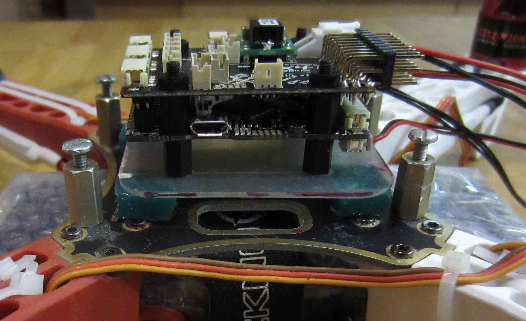
FlameWheel F330 with PX4FMU Mounted on Intermediate platform

The blog Testing simple anti-vibration solutions for GoPro on an ArduCopter has a video demonstrating vibration isolation using Moon Gel on a Go-Pro camera.
3D Printed Anti-Vibration Platform
GuyMcCaldin's 3D Printed vibration mount on Thingiverse using dampers like these.

The mount can be installed using double sided tape, or M3 screws.
3D Printed Anti-Vibration Platform for NAVIO2
Anti-vibration for NAVIO2 can be easily 3D printed. It significantly simplifies mounting and eliminates vibrations. You can find STL files here.
Anti-vibration with Navio2 mounted on frame:

O-ring Suspension Mount
- Create a platform upon which to mount your autopilot with holes or screws on the four corners. Mount your autopilot on this board with double sided foam tape.
- Mount 4 standoffs on the top of your frame spaced 1/10" to 1/8" further apart than the width of the platform upon which the control board has been mounted.
- Insert 1/16" nylon O-rings through each corner of the autopilot and the standoffs so that the autopilot has no hard
connections to the frame.
Link (Here!)
- The overall O-ring diameter should be chosen to firmly retain the board while providing for light to moderate initial but rapidly snubbed movement of the board (generally 1/2" to 3/4" OD) and Silicone O-rings should generally damp better than Buna-N O-rings (Sizes 15 - 21) if you can acquire them.

FlameWheel F450 O-Ring Suspension Platform Mount
Vibrations are short coupled, so all that leaving excess corner clearance does is to require higher initial O-ring tension which reduces vibration damping responsiveness and allows the board to physically tilt more (which is undesirable as it throws the sensor to airframe relationship off).
The disadvantage to O-ring suspension versus Gel pads is that it is mechanically more complex and it requires tuning of both of O-ring diameter and cross section.
You can combine O-ring and gel pad design by using an intermediate plate and benefit from dual rate damping.
Ear Plug Mount
- Purchase slow response silicon or urethane foam or PVC foam earplugs such as these from 3M.
- Create a platform upon which to mount your autopilot with holes at the four corners. The holes should be large enough to allow the ear plugs to be inserted into them but not so loose that the board comes loose during hard landings. Ensure the holes are smooth so they do not cut into the ear plugs. Also keep the holes near the corners of your electronic module plate as possible to minimize unnecessary module movement.
- Mount your autopilot on this board with double sided foam tape. Extra mass added to the board may improve vibration damping.
- Squeeze the earplugs through existing holes in the frame (or cut new holes) and the holes in the board upon which the autopilot is mounted. "Tuning" is possible by varying the amount of earplug left exposed in the middle.

Ear Plug Vibration Mount
Bulb Damper + Ear Plug Vibration Mount
Mounting plate with a 100g soft rubber bulb type "gimbal" damper at each corner and a half a urethane foam earplug placed inside each one.
Gimbal bulb type dampers themselves can work in tension or compression.
The earplugs provide an additional damping medium with a different frequency damping range than the bulb dampers by themselves.
The ear plugs also stiffen the bulb mounts up a bit preventing excessive free motion being caused by normal flight maneuvers.
This was successful at damping a Flamewheel clone with flexible arms and over size 12" propellers into the .05 G range.
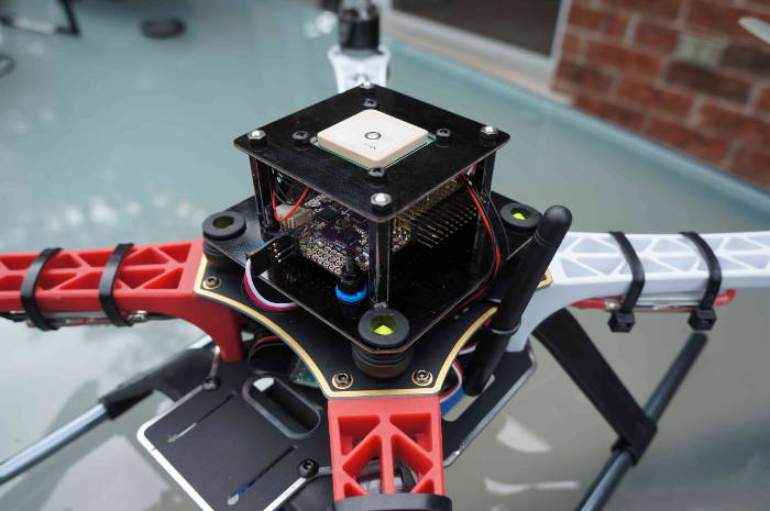
The autopilot is also mounted on anti-vibration grommets available from McMaster Carr (package of 25 each part #9311K64 recommended).
The 100G bulb type gimbal vibration dampers can be ordered direct from a variety of vendors: copter-rc.com


Advice for reducing vibrations
For copters the largest source of vibration is normally the blades passing over the arms but other sources of vibration also exist and may be reduced by following this advice:
- Frame flex especially arm flex is a big cause of asynchronous
vibration, Frame arms should be as rigid as possible.
- Original DJI Flamewheel copters have sufficiently rigid injection molded arms, the many clones do not
- Aluminum or carbon fibre arms twist and bend less which reduces vibrations
- Copters with injection molded exoskeletons or arms like the Iris are sufficiently rigid
- Cheap, light frames tend to flex more than high quality stronger ones and the heavier you load the copter the more flex it gets (not good)
- Motor to frame arm and frame arm to central hub mounts need to be secure and flex free (sometimes a problem for carbon tube arms)
- Motors need to run smoothly (bearings not worn-out or "screeching")
- Prop adapters connecting the propellers to the motors need to be concentric and very straight
- Propellers should be fully balanced using a good manual prop balancer
- Motor balancing (or really well factory balanced motors like T-Motor) can have a major effect
- Propellers that are not well matched to the frame and weight or do not have the same flex for CCW and CW are very problematic
- Good propellers vibrate less
- Carbon fiber props are rigid and vibrate less which reduces vibration but are very sharp which is a major safety hazard
Summary of the vibrations that should be damped
- The vibration frequency and amplitude we primarily need to reduce is a characteristic of the motor / prop units turning at flight speed.
- That is, it is a fairly high frequency with fairly low amplitude.
- This requires that we provide a short coupled damping and isolation range.
- The board itself does not need to have nor benefit from a range of motion that exceeds the amplitude of the vibration.
- Because the board does not apply any force to the airframe, the only thing we need to be concerned with Damping / Isolating is the weight (mass) of the board itself plus the forces applied to it by airframe's normal flight maneuvering.
- Since excellent broad frequency range, high damping materials are available our biggest concern will be to use the proper amount of them to optimally damp our autopilot (too much is just as bad as too little).
- Combining the autopilot and receiver onto a separate vibration damped electronics module "plate" or enclosure can increase the mass of the module making it easier to damp effectively as well as reducing the interconnecting wiring and making the whole system more modular.
Additional Vibration Reduction Considerations
- Hard Disk Drive Anti-Vibration Grommets. can provide sufficient or supplemental vibration reduction
- Significant gains in vibration isolation can also be realized by using a high flex wire and strain relief approach to all wires connected to the autopilot (and using the minimum number of wires necessary as well).
- Some frames have lower than normal vibration characteristics due to frame stiffness / flex and isolated centralized mass can greatly influence motor/prop vibration transfer to the central fight controller.
- Isolation and damping can be improved somewhat by sandwiching the autopilot / enclosure between damping pads on both sides in about twenty percent compression. 30 durometer Sorbothane is actually specified at 15 to 20 percent compression for optimal damping.
- Although 30 durometer Sorbothane seems an excellent candidate, experience indicates that it becomes permanently compressed and is not as effective at vibration reduction as the Gel solutions.
- A link to a Blog about the first APM anti-vibration mounting system to achieve 0.05 G damping (2/20/2013 improved to 0.02 G), a dual zone isolation system, combining O-ring suspension and silicone pad is (Here!)
- Motor balancing can also reduce vibration and especially so for
cheaper or larger motors. Balancing involves:
- Tightly fasten a small tie wrap around a motor (WITH NO PROP), trim off the extended tab and spin it up.
- Try multiple times, each time turning the tie wrap on the motor housing a bit until the vibration reduces or goes away.
- A small piece of Scotch tape can be re-positioned instead of the tie wrap if desired or for smaller motors.
- When you locate the spot where there is the least vibration (and you should be able to hear it), mark the spot directly under the clasp of the tie-wrap with a felt pen.
- Add a small dot of hot glue gun glue where the Tie-Wrap clasp was and increase the glue a bit at a time till the vibration is minimized.
- If you put too much glue on it can be removed with an X-acto knife.
- Camera Mounts also need to be effectively isolated and damped from vibration, but they already have a number of "soft" mounting solutions.
- The camera servos need to be vibration isolated as well, either in the isolated camera mount itself or with their own vibration reduction solution.
- You should use high quality ball joints on your camera servo arms and adequate bearings or bushings in the mount itself with zero free play to prevent inertial slop.
- Quality servos without free play are also a must for precision camera work.
- At this point in time it seems that the more rigid the frame the better because frame flex introduces undesirable mechanical delay (hysteresis) in translating motor induced actions to the centrally located autopilot. (Do NOT shock mount the motor Arms).
- The amount and type of damping medium needs to be carefully matched to the weight (mass) of the item we are trying to isolate as well as the frequency and amplitude of the vibrations we are seeking to damp. We are trying to isolate an autopilot that weighs less than 2 ounces and this is a very small mass.
- Virtually all off the shelf solutions (either pad or stud type) are designed for an isolated mass that would weigh at least 5 to 10 times what an average autopilot weighs for optimal effectiveness. This includes all pre-made Sorbothane, Alpha gel, EAR, memory foam or other silicone or urethane gel or foam mounts as well as Lord Micro mounts.
- A threaded stud or sleeve type mount gel mount properly designed for the mass of our autopilot or electronics module undergoing the stress's of normal flight would be a much better long term solution.
Terminology
The methods used will typically incorporate both damping and isolation:
- Isolation is simple undamped (spring or rubber band support) which allows the movement of the isolated object largely separate from the containing object (Automobile spring for instance).
- Damping is the conversion of vibration into heat energy by a shock absorbing medium (automobile shock absorber for instance).
Links to related discussions
- RC Groups page on Vibration Effects relating to a camera mounts
- DIYDrones discussion related to Vibration Control
- Gary McCray's DIYDrones BLOG re Vibration Control
【本页后半部分仍为英文原文摘录,补译中。】
译自 ArduPilot Copter「Vibration Damping」· 查看原文 · CC BY-SA 3.0